Category Archives: Manuals

foxbody manual steering rack

Foxbody Manual Steering Rack: A Comprehensive Guide (Updated 02/26/2026)

Foxbody steering, utilizing a rack and pinion system, offers direct control. Some racks are prone to leaks, impacting performance and requiring careful attention.

The Foxbody Mustang’s steering system, a cornerstone of its driving experience, traditionally employed a rack and pinion setup – a significant engineering advancement allowing for precise directional control. While power steering was an option, many enthusiasts favor the direct connection offered by a manual steering rack.

This preference stems from a desire for enhanced road feel and a more engaging driving experience. The rack and pinion design itself is inherently efficient, translating steering wheel input directly into wheel movement. However, age and use can introduce issues, like leaks, even in manual systems due to seal degradation. Understanding the nuances of the Foxbody steering system is crucial for maintaining its responsiveness and enjoying the classic Mustang feel.

Why Choose Manual Steering?

Opting for a manual steering rack in your Foxbody Mustang delivers a uniquely connected driving experience. Removing the power steering pump and associated components results in noticeable weight reduction, contributing to improved handling and potentially increased performance. Beyond weight savings, manual steering provides superior steering feel and feedback, allowing drivers to directly sense the road conditions.

Furthermore, a manual setup simplifies the system, reducing potential failure points and offering cost savings – both initially and in long-term maintenance. While requiring more effort at low speeds, the enhanced control and responsiveness often outweigh this drawback for enthusiasts seeking a purist driving experience.

Understanding the Foxbody Steering System

The Foxbody’s steering system, whether equipped with power or manual steering, fundamentally relies on a rack and pinion design. This system translates the rotational motion of the steering wheel into linear motion, directing the front wheels. In a manual setup, driver effort directly actuates the rack, unlike power steering which uses hydraulic assistance.

Key components include the steering column, connecting to the manual steering rack itself. The rack’s movement is then transferred via tie rods to the steering knuckles, ultimately controlling wheel direction. Understanding this interconnectedness is crucial for diagnosis and repair, especially considering potential issues like leaks or play within the system.

Components of the Manual Steering Rack

Essential parts include the rack itself, the steering column connection, the Pitman and idler arms, and tie rods with ball joints, enabling precise control.

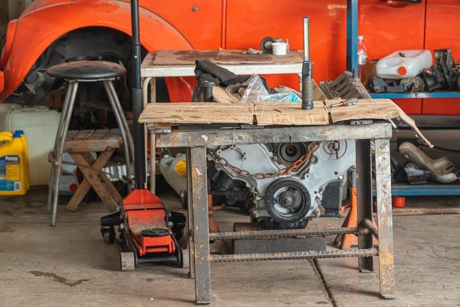
The Manual Steering Rack Itself

The core of the system, the Foxbody manual steering rack, is a robust unit translating rotational motion from the steering column into linear motion. This linear movement directly acts upon the tie rods, initiating the turning of the front wheels. Unlike power steering racks, manual racks lack hydraulic assistance, demanding more driver effort.

Construction typically involves a metal housing containing a pinion gear that meshes with a toothed rack. This design provides a direct and responsive feel, favored by enthusiasts seeking greater road feedback. Inspecting the rack for corrosion, damage to the teeth, or internal leaks (even in manual systems, seals can fail) is crucial during maintenance. A well-maintained rack ensures precise steering and enhances the driving experience.

Steering Column Connection

The steering column’s connection to the manual steering rack is a critical link, transmitting the driver’s input. Typically, a U-joint or rag joint connects the steering shaft to the pinion shaft within the rack housing. This flexible coupling absorbs vibrations and allows for slight misalignment, preventing binding.

Proper alignment is essential; any looseness or play in this connection directly translates to imprecise steering. Inspect the U-joint or rag joint for wear, cracks, or excessive play. Ensuring a secure and properly aligned connection is paramount for responsive steering. Tightening the retaining bolts to the manufacturer’s specifications is vital for safe operation and optimal performance.

Pitman Arm and Idler Arm

In a Foxbody’s manual steering system, the Pitman arm and idler arm play a crucial role in translating the rack’s linear motion into rotational movement for the wheels. The Pitman arm, bolted directly to the steering rack’s sector shaft, converts the rack’s side-to-side motion into a rotating force.

The idler arm, positioned on the opposite side of the steering box, supports the center link and helps maintain steering stability. Worn ball joints in either arm introduce play, leading to imprecise steering and potential safety concerns. Regular inspection and replacement of these components are vital for maintaining a responsive and reliable steering system.

Tie Rods and Ball Joints

Tie rods and ball joints are critical links in the Foxbody’s manual steering system, directly connecting the steering rack to the wheels. Inner and outer tie rods transmit the steering force, while ball joints allow for smooth, controlled wheel movement. These components are subject to significant stress and wear, particularly from road impacts and consistent use.

Worn tie rod ends or ball joints introduce play into the steering, resulting in imprecise handling and potential instability. Regular inspection for looseness or damage is essential. Replacement should occur in pairs to ensure balanced steering geometry and optimal performance, maintaining safe and predictable vehicle control.

Benefits of a Manual Steering Rack Upgrade

Upgrading to a manual rack reduces weight, enhances steering feel, and provides a more direct connection to the road for improved control.

Improved Steering Feel and Feedback

Switching to a manual steering rack on your Foxbody dramatically alters the driving experience, prioritizing feel and feedback over power assistance. Unlike power steering systems that can mask road imperfections, a manual rack transmits a more direct connection to the road surface.

This heightened sensitivity allows drivers to intuitively understand what the front tires are doing, enhancing control and confidence, especially during spirited driving or track use. You’ll notice subtle changes in road texture and grip, providing valuable information for precise steering inputs.

The removal of hydraulic lines and the power steering pump also contributes to a cleaner, more responsive steering action, eliminating any potential lag or artificial weighting. This results in a more engaging and rewarding driving experience for enthusiasts.

Weight Reduction

One of the most significant benefits of converting to a manual steering rack on a Foxbody Mustang is the substantial weight savings. Eliminating the power steering pump, hydraulic lines, reservoir, and associated hardware removes a considerable amount of unnecessary mass from the front end of the vehicle.

This reduction in weight directly improves the car’s overall handling characteristics, contributing to quicker steering response and reduced body roll. Less weight over the front wheels also enhances traction, particularly during acceleration and braking.

For performance-oriented builds, where every pound counts, this weight reduction can translate into measurable gains on the track or during autocross events. It’s a simple yet effective modification for maximizing the Foxbody’s potential.

Cost Savings

Switching to a manual steering rack on a Foxbody Mustang presents a compelling financial advantage. The initial cost of a manual rack is typically lower than a comparable power steering unit. Beyond the initial purchase, significant long-term savings are realized by eliminating the potential for costly repairs associated with power steering components.

Power steering pumps can fail, hydraulic lines can leak, and steering gears can develop internal issues – all requiring expensive replacements. A manual system, being simpler in design, reduces the number of potential failure points, leading to lower maintenance costs over the vehicle’s lifespan.

This makes it an attractive option for budget-conscious enthusiasts.

Common Issues with Foxbody Manual Steering Racks

Foxbody manual racks can develop leaks from seals, exhibit steering play due to wear, and suffer corrosion. Tie rod ends also commonly wear out.

Leaks and Fluid Loss (Even in Manual Systems ౼ Seals)

While a manual steering system doesn’t utilize pressurized hydraulic fluid like power steering, leaks can still occur within the rack itself. These aren’t fluid-powered leaks, but rather seepage past the internal seals. Over time, the rubber seals within the Foxbody manual steering rack can dry out, crack, or become brittle due to age and temperature fluctuations.

This deterioration allows steering fluid – used for lubrication within the manual rack – to escape. Though not impacting steering assist, these leaks indicate internal wear and potential for further issues. Identifying leaks early is crucial; look for dampness around the rack housing and connections. Ignoring them can lead to increased wear and eventual rack failure, necessitating a replacement. Regular inspection is key to preventative maintenance.

Play in the Steering

Excessive play in the steering of your Foxbody indicates looseness within the manual steering system. This manifests as noticeable movement in the steering wheel before the front wheels respond. Internal wear within the rack itself is a primary culprit, as clearances increase between components like the pinion gear and rack gear.

Worn tie rod ends, ball joints, or even the idler arm can also contribute to this issue, amplifying the sensation of play. It’s crucial to differentiate between play originating from the rack versus these external components. Significant play compromises steering precision and responsiveness, impacting handling and driver confidence. Addressing this promptly is vital for safe vehicle operation and enjoyable driving.

Corrosion and Rust

Foxbody steering racks, particularly those exposed to harsh climates and road salt, are susceptible to corrosion and rust. This is especially true for older vehicles where preventative maintenance may have been lacking. Rust can form on the exterior of the rack, but more critically, it can attack internal components, leading to scoring and binding.

This internal corrosion increases friction, making steering heavier and less smooth. Advanced rust can even cause pitting and weakening of the rack housing, potentially leading to failure. Regular inspection and protective coatings can mitigate this issue, extending the rack’s lifespan and maintaining optimal steering performance. Ignoring corrosion invites costly repairs.

Worn Tie Rod Ends

Foxbody manual steering relies heavily on precise tie rod end function. Over time, these crucial components experience wear and tear from constant movement and road impacts. Worn tie rod ends introduce excessive play into the steering system, manifesting as vagueness and imprecise handling. This looseness can also cause uneven tire wear and difficulty maintaining a straight line.

Inspecting tie rod ends for looseness and damage is vital during routine maintenance. Symptoms include clunking noises during steering and a noticeable wobble in the front wheels. Replacing worn tie rod ends restores steering accuracy and improves overall vehicle safety, ensuring responsive control.

Replacing Your Foxbody Manual Steering Rack: A Step-by-Step Overview

Rack replacement demands specific tools and careful procedure. Proper removal, installation, and subsequent wheel alignment are critical for optimal steering performance and safety.

Tools Required

Successfully replacing your Foxbody’s manual steering rack necessitates a well-equipped toolkit. Essential items include a jack and jack stands for safe vehicle elevation, and a comprehensive socket set – both metric and standard – to handle various fasteners.

You’ll also need wrenches, specifically flare nut wrenches to avoid damaging the steering lines. A steering rack puller is crucial for safely separating the old rack from the vehicle. Don’t forget penetrating oil to loosen stubborn bolts, and a torque wrench to ensure proper tightening during reinstallation.

A drain pan is needed for any residual fluid, and safety glasses are paramount. Finally, having a rubber mallet and a set of pliers can prove invaluable during the process. Preparation is key for a smooth and efficient replacement!

Removal of the Old Rack

Begin by safely lifting the Foxbody and securing it with jack stands. Disconnect the tie rod ends from the steering knuckles, carefully noting their positions. Next, detach the steering column from the rack, usually involving a U-joint or rag joint.

Loosen and remove the mounting bolts securing the steering rack to the frame. Utilize a steering rack puller to gently separate the rack from the vehicle, avoiding forceful maneuvers that could damage surrounding components.

Pay attention to any lines or hoses connected to the rack, and cap them to prevent contamination. Once free, carefully maneuver the old rack out from under the vehicle, preparing for the installation of the new unit.

Installation of the New Rack

Carefully position the new manual steering rack into place, aligning it with the mounting points on the Foxbody’s frame. Secure it using the original mounting bolts, tightening them to the manufacturer’s specified torque. Reconnect the steering column to the rack, ensuring proper alignment of the U-joint or rag joint.

Attach the tie rod ends, mirroring the original positions noted during removal. Double-check all connections for security. Cap any open lines previously disconnected. Lower the vehicle gently, and then re-torque all bolts after a brief test drive.

This ensures everything settles correctly and maintains optimal steering performance.

Alignment After Installation

Post-installation, a professional wheel alignment is absolutely crucial for optimal handling and tire wear. Manual steering racks, even new ones, can introduce slight variations requiring precise adjustment. This process ensures the vehicle tracks straight and the steering wheel remains centered.

Specifically, camber, caster, and toe angles must be verified and adjusted to factory specifications for your Foxbody model year. Improper alignment can lead to uneven tire wear, reduced handling performance, and even steering instability.

Don’t skip this step; it’s a vital investment in safety and longevity.

Choosing the Right Manual Steering Rack for Your Foxbody

Selecting a rack involves considering OEM versus aftermarket options, desired gear ratios, and ensuring compatibility with your specific Foxbody’s production year.

Aftermarket Options vs. OEM

Original Equipment Manufacturer (OEM) racks provide a direct replacement, ensuring fit and function mirroring the factory specifications for your Foxbody. They offer reliability and are generally a safe bet for a restoration or maintaining a stock feel. However, OEM racks can be harder to find in good condition and may not offer performance enhancements.

Aftermarket options, conversely, often prioritize performance improvements. These racks may feature quicker steering ratios, stronger internal components, or designs aimed at reducing weight. Brands like Flaming River and Borgeson offer various choices. While potentially enhancing handling, aftermarket racks require careful research to confirm compatibility and may necessitate modifications to your Foxbody’s steering system. Consider your driving style and intended use when deciding between OEM and aftermarket.

Gear Ratio Considerations

Gear ratio significantly impacts steering effort and responsiveness in your Foxbody’s manual steering system. A lower ratio (e.g., 12:1) means fewer rotations of the steering wheel are needed for a given wheel turn, resulting in quicker, more direct steering. This is ideal for track use or aggressive driving, but requires more muscle.

Higher ratios (e.g., 16:1 or 20:1) offer easier steering at low speeds, making them suitable for street driving and parking. However, they demand more wheel rotation for the same steering input. Carefully assess your driving needs. A stock Foxbody typically uses a ratio around 16:1. Changing this ratio alters the steering feel dramatically, so consider the trade-offs between effort and responsiveness.

Compatibility with Your Foxbody Year

Foxbody Mustangs (1979-1993) experienced minor steering component variations throughout their production run. While most manual steering racks are broadly interchangeable, subtle differences exist. Early models (1979-1986) may have slightly different mounting points or hose connections compared to later ones (1987-1993).

Always verify compatibility with your specific year and model before purchasing a replacement rack. Cross-referencing part numbers is crucial. Some aftermarket racks are designed as universal fits, requiring minor adjustments. Ensure the steering column connection and tie rod end tapers match your Foxbody’s specifications to avoid installation headaches and ensure proper alignment.

Maintenance and Care for Your Manual Steering Rack

Regular inspections are vital for longevity. Check for leaks around seals and connections, and protect components from corrosion with appropriate coatings.

Regular Inspection

Consistent visual checks are paramount for a healthy Foxbody manual steering rack. Begin by carefully examining the rack itself and all connected lines for any signs of fluid leakage, even in a manual system where seals are critical. Pay close attention to the areas where the steering column connects and where the tie rods attach.

Next, inspect the tie rod ends for play or damage. Excessive movement indicates wear and potential steering issues. Also, thoroughly check the pitman and idler arms for looseness or corrosion. A rusty or damaged arm can significantly affect steering precision.

Finally, routinely assess the steering linkage for any bent or broken components. Early detection of these issues prevents more substantial problems down the road, ensuring safe and responsive handling.

Lubrication

While a manual steering rack doesn’t utilize hydraulic fluid, lubrication remains crucial for longevity. Focus on the moving parts – specifically, the steering column connection and the ball joints within the tie rod ends. These areas experience significant friction during operation.

Apply a high-quality chassis grease to the ball joints regularly, ensuring thorough coverage. For the steering column connection, a light coating of grease will minimize wear and prevent binding. Avoid over-greasing, as excess lubricant can attract dirt and debris.

Consistent lubrication reduces friction, promotes smooth operation, and extends the lifespan of these vital components, contributing to precise steering and a more enjoyable driving experience.

Protecting Against Corrosion

Foxbody steering components are susceptible to corrosion, especially in regions with harsh winters or coastal climates. Road salt and moisture accelerate rust formation on the manual steering rack, tie rods, and other exposed parts.

Regularly wash the undercarriage of your Foxbody, paying close attention to the steering system. Apply a rust inhibitor or undercoating to create a protective barrier against the elements. Inspect components for existing rust and address it promptly with a wire brush and rust converter.

Preventative measures significantly extend the life of your steering system, ensuring reliable performance and avoiding costly repairs down the road.

Troubleshooting Common Manual Steering Problems

Diagnosing issues like steering play or noise is crucial for maintaining a responsive Foxbody. Identifying leaks promptly prevents further damage to the system.

Diagnosing Steering Play

Excessive steering play in a Foxbody’s manual rack indicates looseness within the system. Begin by securely jacking up the front end, ensuring the wheels are off the ground. Grasp the steering wheel and attempt to move it side-to-side without the wheels turning. Any noticeable movement before the wheels respond signifies play.

Inspect the tie rod ends for wear; looseness here is a common culprit. Also, carefully examine the manual steering rack itself for internal damage or worn components. A mechanic’s stethoscope can help pinpoint noise originating from the rack. Remember to check the Pitman arm and idler arm connections for any slack. Addressing play promptly improves handling and prevents further wear on steering components, ensuring a safer driving experience.

Addressing Noisy Steering

Unusual noises during steering on a Foxbody often point to specific issues. Groaning sounds can indicate a lack of lubrication within the manual steering rack, or potentially worn internal components. Clicking or popping noises frequently originate from worn tie rod ends or ball joints. A high-pitched whine might suggest air entering the system, even in a manual setup, potentially through deteriorated seals.

Carefully inspect all steering linkage connections for tightness. Use a stethoscope to isolate the noise source. Regularly lubricating the steering components can alleviate some noises. If the noise persists, a thorough inspection of the rack and associated parts is crucial to prevent further damage and maintain safe steering control.

Identifying Potential Leaks

Although manual steering doesn’t utilize hydraulic fluid like power steering, leaks can still occur. These aren’t fluid leaks, but rather seepage from the steering rack seals, allowing dirt and debris to enter. Inspect the rack housing and boots for any signs of grease or grime expulsion. Look closely at the steering column connection and where the tie rods attach.

Even small amounts of contamination can accelerate wear. Check for dampness around the rack mounts. While not a fluid leak, compromised seals diminish the rack’s lifespan. Address any seal deterioration promptly to prevent internal damage and maintain optimal steering performance. Regular visual inspections are key.

q990c manual

The Samsung HW-Q990C, a 2023 flagship model, delivers immersive audio with a substantial 11.1.4 channel configuration and powerful bass capabilities for a cinematic experience.

Overview of the HW-Q990C

The Samsung HW-Q990C stands as the company’s premier soundbar offering for 2023, engineered to deliver a truly immersive and powerful home theater audio experience. This flagship model boasts an impressive 11.1.4 channel setup, promising expansive sound that fills any room. It’s designed not just for volume, but for nuanced audio reproduction, aiming to replicate the cinematic soundscapes of a dedicated home theater.

A key aspect of the Q990C is its advanced technology, including the latest generation of Q Symphony. This feature intelligently coordinates sound output between the soundbar and compatible Samsung TVs, utilizing all speakers for a more cohesive and dynamic soundstage – a significant improvement over previous iterations. Expect a substantial investment, as this is positioned as a top-tier product, but one that aims to justify its price with exceptional performance and features.

Key Features and Specifications

The HW-Q990C’s core strength lies in its 11.1.4 channel configuration, supporting Dolby Atmos and DTS:X for a truly three-dimensional sound experience. It features up-firing speakers for height effects, combined with dedicated side and rear channels for immersive surround sound. The third-generation Q Symphony technology optimizes speaker coordination with compatible Samsung TVs, maximizing audio output.

Connectivity options include HDMI eARC, optical input, and potentially Bluetooth. While specific power output figures vary, the Q990C is designed to deliver substantial volume and impactful bass. Notably, the wireless rear speakers have strategically placed wireless chips to minimize interference. Design-wise, it presents a more grey-ish aesthetic compared to the pure black finish of the Q990B, offering a subtle visual difference.

Setting Up Your HW-Q990C

Proper setup involves unboxing all components, connecting to your Samsung TV via HDMI eARC, and strategically positioning the wireless rear speakers for optimal sound.

Unboxing and Component Check

Carefully unpack the HW-Q990C soundbar package, ensuring all components are present. You should find the main soundbar unit, two wireless rear speakers, a wireless subwoofer, power cables for each unit, an HDMI cable, and the user manual.

Inspect each item for any physical damage that may have occurred during shipping. Verify the presence of all cables and accessories listed in the included documentation. Pay close attention to the wireless rear speakers, confirming both the left and right units are included.

Before proceeding with the connection process, familiarize yourself with the ports located on the back of the soundbar and subwoofer. Retain the original packaging for potential future transport or warranty claims.

Connecting to Your Samsung TV

For optimal performance, connect the HW-Q990C to your Samsung TV using the provided HDMI eARC (Enhanced Audio Return Channel) cable. This ensures lossless audio transmission and enables features like Q Symphony. Locate the HDMI eARC port on both your TV and the soundbar – it’s typically labeled.

If your TV doesn’t have an eARC port, you can use a standard HDMI port, but audio features may be limited. Alternatively, an optical audio cable can be used, though it doesn’t support the full bandwidth of eARC.

Once connected, navigate to your TV’s sound settings and select the soundbar as the audio output device. Enable eARC in the TV settings if prompted.

Wireless Rear Speaker Placement

Optimal placement of the wireless rear speakers is crucial for a truly immersive sound experience with the HW-Q990C. Position the speakers behind the listening area, angled slightly inwards towards the main listening position. Ensure they are at ear level or slightly above for the best soundstage.

Avoid obstructions that might block the wireless signal. The Q990C’s wireless chip placement – left side for the left speaker, right side for the right – aims to minimize interference.

Maintain a reasonable distance from the soundbar; excessive distance can weaken the wireless connection. Experiment with positioning to find the sweet spot for your room’s acoustics.

Understanding the HW-Q990C’s Sound Technology

The HW-Q990C utilizes 11.1.4 channel sound with Dolby Atmos, alongside Q Symphony, to deliver a powerfully immersive and coordinated audio experience.

11.1.4 Channel Sound and Dolby Atmos

The Samsung HW-Q990C boasts an impressive 11.1.4 channel sound system, signifying eleven speakers, one subwoofer, and four up-firing channels for Dolby Atmos. This configuration creates a truly immersive soundscape, enveloping the listener with detailed and directional audio. Dolby Atmos expands on traditional surround sound by adding height channels, allowing sounds to move overhead, replicating a cinematic experience within your home.

The inclusion of up-firing speakers bounces sound off the ceiling, simulating overhead audio even without ceiling-mounted speakers. This technology, combined with the numerous channels, delivers a heightened sense of realism and spatial accuracy. The 11.1.4 setup ensures that every sound effect, musical note, and dialogue is delivered with clarity and precision, enhancing the overall viewing and listening experience. It’s designed to provide a powerful and dynamic audio performance.

Q Symphony: Advanced Speaker Coordination

Samsung’s Q Symphony technology represents a significant advancement in speaker coordination, uniquely available when paired with compatible Samsung TVs. Unlike previous iterations that utilized only selected speakers, the third-generation Q Symphony on the HW-Q990C leverages every speaker within both the soundbar and the connected Samsung TV simultaneously.

This full utilization of speakers results in a more powerful and immersive audio experience, creating a wider and more cohesive soundstage. Q Symphony optimizes audio output by intelligently distributing sound signals, ensuring that each speaker contributes to the overall sonic performance. This coordinated effort minimizes interference and maximizes clarity, delivering a richer, more detailed, and truly enveloping sound experience that elevates home entertainment.

Enhanced Bass Performance

The Samsung HW-Q990C is engineered to deliver a truly impactful and room-filling bass experience, enhancing the overall cinematic immersion. Reviews consistently highlight the soundbar’s ability to produce substantial low-frequency effects, capable of adding significant weight and depth to action sequences and musical scores.

While not literally liquefying innards as some playfully suggest, the Q990C’s bass performance is described as powerful and punchy. This is achieved through a combination of its robust amplifier, carefully tuned drivers, and the overall 11.1.4 channel configuration. The dedicated subwoofer works in harmony with the soundbar to create a balanced and dynamic low-end response, ensuring that bass frequencies are felt as much as they are heard, elevating the home theater experience.

Connectivity and Ports

The HW-Q990C boasts solid connectivity options, including HDMI eARC, optical input, and other connections, ensuring compatibility with various home theater setups.

HDMI eARC Connection

Utilizing the HDMI eARC (Enhanced Audio Return Channel) connection is highly recommended for optimal performance with the Samsung HW-Q990C soundbar. This advanced HDMI feature allows for the transmission of high-bitrate, lossless audio formats – such as Dolby Atmos and DTS:X – directly from your compatible TV to the soundbar, bypassing any potential limitations of standard ARC.

To establish an eARC connection, ensure both your Samsung TV and the HW-Q990C support eARC. Connect an HDMI cable to the HDMI eARC port on both devices. Within your TV’s settings, enable eARC functionality; the specific menu location will vary depending on your TV model. Once enabled, the soundbar will automatically detect the eARC connection and deliver the highest quality audio available from your source content, providing a truly immersive and dynamic soundscape.

Optical Input and Other Connections

While HDMI eARC is preferred, the Samsung HW-Q990C also offers an optical input for compatibility with older TVs or devices lacking HDMI eARC support. The optical connection transmits digital audio, though it may not support the full bandwidth of lossless formats like Dolby Atmos.

Additionally, the soundbar features other connectivity options, potentially including a USB port for service updates or media playback. Carefully consult the included manual for specific port locations and functionalities; Remember that utilizing the optical input may require adjusting audio settings on both your TV and the soundbar to ensure proper signal transmission and optimal sound quality. Prioritize HDMI eARC whenever possible for the best audio experience.

Troubleshooting Common Issues

Users report potential issues with power cable length, wireless speaker interference, and sound synchronization; consulting the manual and checking connections are crucial first steps.

Power Cable Length and Solutions

Many Samsung HW-Q990C owners have encountered a common issue: the provided power cables for the rear wireless speakers are often too short for optimal placement. This is particularly true when outlets aren’t conveniently located near the desired speaker positions, often requiring extension cords. Users have actively sought longer replacement cables, sharing product codes and links online to assist others facing the same challenge.

If you find yourself needing a longer cable, ensure it’s adequately rated for the soundbar’s power requirements to avoid safety hazards. Consider a heavy-duty extension cord or purchasing a dedicated longer power cable specifically designed for audio equipment. Prioritize safety and avoid overloading circuits when using extensions. Carefully route the cables to prevent tripping hazards and maintain a clean setup.

Wireless Speaker Interference

A notable design feature of the HW-Q990C aims to minimize wireless interference. The left surround speaker’s wireless chip is positioned on the left side of the soundbar, while the right surround speaker’s chip resides on the right. This strategic placement is intended to reduce potential signal disruptions and ensure a stable connection between the main unit and the rear speakers.

However, interference can still occur due to other wireless devices, physical obstructions (like thick walls), or distance. If you experience dropouts or connectivity issues, try repositioning the speakers or the soundbar itself. Minimize obstructions and keep the distance within the recommended range. Reducing interference from other devices, such as routers or microwaves, can also improve performance.

Sound Synchronization Problems

Occasionally, users may encounter sound synchronization issues where the audio doesn’t align perfectly with the video. This can be frustrating, disrupting the immersive experience the HW-Q990C is designed to deliver. Several factors can contribute to this problem, including delays introduced by your TV’s processing or the HDMI connection itself.

To address this, first, check your TV’s audio settings for any delay adjustments (often labeled as ‘Audio Delay’ or ‘Lip Sync’). Experiment with these settings to find the optimal synchronization. Ensure you’re using a high-quality HDMI cable and that it’s securely connected. If using HDMI eARC, verify that eARC is properly enabled in both your TV and soundbar settings. A software update for both devices can also resolve synchronization glitches.

Comparing the Q990C to Other Models

The Q990C distinguishes itself with a higher channel count and advanced third-generation Q Symphony, offering superior sound compared to models like the Q930C.

Q990C vs. Q930C

When considering the Samsung HW-Q990C and HW-Q930C, the primary difference lies in their speaker configurations and resulting audio performance. The Q990C boasts an 11.1.4 channel system, providing a more expansive and immersive soundstage compared to the Q930C.

Many potential buyers question if the price jump to the Q990C is justified, particularly for smaller rooms or less demanding audio setups. While both models deliver excellent sound quality, the Q990C’s additional speakers contribute to a more detailed and enveloping experience, especially with Dolby Atmos content.

Essentially, the Q930C remains a fantastic option, but the Q990C represents the pinnacle of Samsung’s 2023 soundbar lineup, offering a noticeable step up in sonic fidelity and overall immersion for those seeking the ultimate home theater audio solution.

Q990C vs. Q990B (Design Differences)

Visually, the Samsung HW-Q990C presents subtle yet noticeable design refinements compared to its predecessor, the HW-Q990B. While both models share a similar overall aesthetic, the Q990C adopts a more greyish hue, diverging from the pure black finish of the Q990B.

Furthermore, a key internal design change involves the placement of the wireless chips within the rear surround speakers. The Q990C strategically positions the wireless chip on the left side of the left surround speaker and on the right side of the right surround speaker.

This deliberate placement aims to minimize potential wireless interference, potentially leading to a more stable and reliable connection between the soundbar and its satellite speakers, enhancing the overall audio experience.

Advanced Settings and Customization

Users can fine-tune their audio experience with the Q990C through detailed equalizer settings and selectable sound modes, tailoring the sound to their preferences.

Equalizer Settings

The Samsung HW-Q990C provides users with comprehensive control over the audio frequencies, allowing for precise customization of the sound profile. Within the soundbar’s settings menu, accessible via the remote control or the SmartThings app, you’ll find a multi-band equalizer.

This allows adjustment of specific frequency ranges – typically bass, mid-range, and treble – to enhance clarity, boost bass response, or reduce harshness. Users can manually adjust each band to their liking, or select from pre-set equalizer profiles designed for different content types, such as movies, music, or voice.

Experimentation is encouraged to achieve the optimal sound for individual preferences and room acoustics. Saving custom profiles allows quick switching between tailored sound settings for various listening scenarios.

Sound Mode Selection

The HW-Q990C offers a variety of pre-programmed sound modes designed to optimize the audio experience for different types of content. Accessible through the soundbar’s remote or the SmartThings app, these modes include ‘Standard,’ ‘Surround,’ ‘Game Pro,’ and ‘Adaptive.’

‘Standard’ delivers balanced audio suitable for general viewing, while ‘Surround’ expands the soundstage for a more immersive cinematic effect. ‘Game Pro’ minimizes audio latency and enhances directional cues for gaming, and ‘Adaptive’ intelligently analyzes the content and adjusts the sound settings accordingly.

Additionally, a ‘Voice Enhance’ mode clarifies dialogue, and a ‘Night Mode’ reduces dynamic range for quieter listening. Experimenting with these modes allows users to quickly find the best audio experience for their current activity.

chamberlain liftmaster professional 1 3 hp instruction manual

Chamberlain LiftMaster Professional 1 1/3 HP: A Comprehensive Guide

This guide details the Chamberlain LiftMaster 1 1/3 HP opener, covering installation, safety, programming, and troubleshooting.
It references official documentation and accessories like the GDC1s enclosure and 940EV keyless entry systems, ensuring proper usage.

The LiftMaster Professional 1 1/3 HP garage door opener represents a robust solution for residential use, offering reliable performance and advanced features. This opener, manufactured by Chamberlain, is designed for sectional and one-piece doors, demanding careful installation following the provided owner’s manual. Understanding the system’s capabilities, including compatibility with accessories like the 940EV wireless keyless entry, is crucial.

This guide serves as a companion to the official Chamberlain documentation, offering detailed insights into installation steps, safety precautions, programming procedures, and troubleshooting common issues. Proper citation of Chamberlain resources – including websites and manuals – is emphasized. The 1 1/3 HP model benefits from the GDC1s enclosure for enhanced connectivity, and its operation requires adherence to safety guidelines for optimal functionality and longevity.

Understanding the Model Number and Compatibility

The LiftMaster Professional 1 1/3 HP model number signifies its power and intended application. Compatibility extends to various garage door types, including sectional and one-piece designs, though installation procedures differ. Crucially, this opener functions with Chamberlain garage door openers manufactured after January 1, 1993, and supports 315 MHz or 390 MHz frequencies.

Accessory compatibility is a key feature; the 940EV/940EVC wireless keyless entry systems integrate seamlessly. The GDC1s enclosure enhances connectivity, enabling smart home integration. Referencing the instruction manual is vital to confirm compatibility with specific door weights and sizes. Proper understanding of these specifications ensures optimal performance and avoids potential operational issues, maximizing the lifespan of your LiftMaster system.

Safety Precautions & Warnings

Prioritize safety during installation and operation. Always disconnect power before servicing, understand emergency release procedures, and review all safety information within the owner’s manual.

General Garage Door Opener Safety

Garage door openers are powerful devices, and adhering to safety guidelines is crucial. Never allow children to operate the opener or play near the door. Regularly inspect the door’s balance using the manual release; a properly balanced door should remain stationary midway.

Keep the area around the door clear of obstructions. Never operate the opener while anyone is passing through the door. Test the safety reversal system monthly – the door should immediately reverse upon encountering an obstacle in its path.

Ensure all safety sensors are properly aligned and unobstructed. Disconnect power before making any repairs or adjustments. Familiarize yourself with the emergency release mechanism for manual operation in case of power outages. Always consult the full owner’s manual for comprehensive safety instructions.

Specific Safety Concerns for the 1 1/3 HP Model

The 1 1/3 HP LiftMaster Professional offers increased lifting power, necessitating extra caution. Due to its strength, ensure the garage door itself is appropriately rated to handle the increased force; improper door selection could lead to damage or failure.

Pay close attention during force setting adjustments – excessive force can compromise safety features. Regularly verify the sensitivity of the safety sensors, as a more powerful motor might require finer tuning.

When installing accessories like the GDC1s enclosure, confirm compatibility and secure wiring to prevent interference with safety systems. Always prioritize a thorough understanding of the manual and heed all warnings regarding the opener’s enhanced capabilities.

Emergency Release Procedures

In emergencies, the LiftMaster 1 1/3 HP opener features a manual release mechanism. Locate the emergency release cord, typically hanging from the central rail. Pulling this cord disengages the motor, allowing manual operation of the garage door – exercise caution, as the door may be heavy.

After disengaging, the door can be lifted or lowered by hand. To re-engage, simply pull the cord towards the opener until it clicks back into place. Always test the opener’s functionality after re-engagement to ensure proper operation.

Familiarize yourself with this procedure before an emergency arises. Refer to the instruction manual for specific illustrations and warnings related to the release mechanism.

Installation Guide

Proper installation is crucial. This section details unboxing, inventory, and step-by-step instructions for both sectional and one-piece doors, ensuring safe and effective operation.

Unboxing and Inventory of Parts

Carefully unpack the Chamberlain LiftMaster 1 1/3 HP opener box, ensuring all components are present before proceeding. The opener carton inventory should include the power unit, rail sections, chain or belt drive, safety sensors, remote controls, mounting hardware, and the instruction manual itself.

Verify each item against the parts list within the manual to confirm nothing is missing. Pay close attention to smaller components like bolts, nuts, and washers, as these are easily misplaced. Inspect all parts for any shipping damage. If any parts are damaged or missing, contact Chamberlain customer support immediately for replacements. Retain the original packaging until the installation is complete and you are satisfied with the product. A complete inventory prevents delays during the installation process.

Sectional Door Installation Steps

Begin by assembling the rail sections, connecting them securely according to the manual’s diagrams. Attach the rail to the header bracket above the sectional door, ensuring it’s level and properly aligned. Next, connect the door bracket to the bottom of the door, and then attach the arm to both the door bracket and the opener carriage.

Carefully follow the manual’s instructions for adjusting the door arm length to ensure smooth operation. Install the safety sensors on both sides of the door opening, at the recommended height, and connect the wiring to the opener unit. Double-check all connections and ensure the door moves freely before proceeding to programming. Proper alignment is crucial for safe and reliable operation.

One-Piece Door Installation Steps

Installing on a one-piece door requires specific bracing and reinforcement due to the door’s construction. Begin by securely mounting the header bracket to the ceiling joists, ensuring it can support the door’s weight. Attach the door bracket directly to the door itself, using appropriate hardware for a strong connection.

Connect the opener arm between the door bracket and the carriage, carefully adjusting the arm length as detailed in the manual. One-piece doors often require precise adjustments to ensure smooth lifting and lowering. Install and wire the safety sensors, verifying their proper function. Thoroughly test the operation, paying close attention to any binding or resistance, and adjust accordingly.

Mounting the Opener Unit

Securely mounting the opener unit is crucial for stable operation. Begin by assembling the rail sections, ensuring proper alignment and connection. Position the assembled rail and opener unit beneath the ceiling, utilizing the pre-drilled holes for mounting brackets. Attach the brackets to ceiling joists using lag screws or bolts, verifying they are firmly secured.

Carefully lift the opener unit onto the mounted brackets, aligning the mounting points. Double-check that all connections are tight and secure before proceeding. Connect the electrical power supply, adhering to all safety precautions. Finally, verify the unit is level and stable before initiating programming and testing procedures.

Programming & Settings

Customize your LiftMaster with remote programming, travel limit adjustments, and force settings. Enable MyQ connectivity for smartphone control and advanced features.

Remote Control Programming

Programming your LiftMaster remote is straightforward. Begin by ensuring the opener is compatible with your remote’s frequency (315 MHz or 390 MHz, post-1993). Locate the “Learn” button on the opener unit – it’s typically yellow or orange. Press and release this button. Within 30 seconds, press and hold the button on your remote until the opener’s light flashes, indicating successful programming.

If multiple remotes need programming, repeat this process for each one. For older remotes, consult the specific remote’s manual for alternative programming methods. If programming fails, try clearing existing remote codes by pressing and holding the “Learn” button until the light goes out, then re-attempt the programming sequence. Always refer to the Chamberlain/LiftMaster instruction manual for detailed, model-specific instructions.

Travel Limit Adjustment

Adjusting travel limits ensures the door opens and closes to your desired heights. Locate the adjustment dials on the opener unit – typically labeled “Up” and “Down”. Use a screwdriver to make small adjustments. Clockwise rotation increases the travel distance, while counterclockwise decreases it.

Start with minor adjustments and test the door’s operation after each change. The “Up” limit controls how far the door opens, while the “Down” limit sets the closed position. Ensure the door doesn’t reverse prematurely or travel beyond its intended limits. Refer to the instruction manual for specific dial sensitivity information. Precise adjustment prevents strain on the door and opener, extending their lifespan.

Force Setting Adjustment

Force settings dictate the power applied to overcome door resistance. Locate the force adjustment dials, usually marked “Up/Down” or with a similar designation, on the opener unit. These control the power used during closing and opening. Adjusting these settings is crucial for smooth operation and safety.

Start with the lowest force setting and gradually increase it until the door operates smoothly without reversing unexpectedly. Avoid excessive force, as it can damage the door or opener. The manual details specific settings for different door weights and conditions. Proper adjustment ensures the safety sensors function correctly, preventing the door from closing on obstructions. Regularly check these settings for optimal performance.

MyQ Connectivity & Setup

MyQ technology enables remote control and monitoring of your garage door via a smartphone app. Begin by downloading the MyQ app from your device’s app store. Ensure your opener is compatible – most LiftMaster Professional 1 1/3 HP models are. The GDC1s enclosure, when used, facilitates a stable connection.

Follow the in-app instructions to create an account and connect your opener. The app will guide you through the process of linking the opener to your home’s Wi-Fi network. Once connected, you can open/close the door, receive activity alerts, and set schedules. Refer to the manual for specific troubleshooting steps if the connection fails. MyQ enhances security and convenience.

Maintenance & Troubleshooting

Regular maintenance ensures optimal performance. This section covers schedules, motor noise issues, remote control problems, and unexpected door reversals, referencing the manual.

Regular Maintenance Schedule

Maintaining your Chamberlain LiftMaster 1 1/3 HP opener is crucial for longevity and safety. A monthly visual inspection should be performed, checking for loose hardware, frayed cables, and proper spring tension. Lubricate all moving parts – rollers, hinges, and the opener’s chain or belt drive – every six months using a lithium-based grease.

Test the safety reversal system monthly by placing a one-inch object in the door’s path. The door should immediately reverse. Inspect the photo-eye sensors, ensuring they are aligned and free from obstructions. Clean the sensors with a soft cloth. Annually, tighten all bolts and nuts. Refer to the owner’s manual for detailed diagrams and specific lubrication points. Following this schedule minimizes potential issues and ensures reliable operation.

Troubleshooting Common Issues (Motor Noise)

Excessive motor noise often indicates a few common problems. First, check the chain or belt drive; it may require lubrication. A noisy motor could also stem from loose mounting brackets – tighten all bolts. Inspect the rollers and tracks for obstructions or damage, as these can cause strain and noise.

If the noise is a grinding sound, the gears within the opener unit might be worn and require professional attention. Humming without movement suggests a potential issue with the capacitor. Always disconnect power before inspecting internal components. Consult the owner’s manual for diagrams and safety precautions. If the noise persists after these checks, contact a qualified technician.

Troubleshooting Common Issues (Remote Not Working)

A non-responsive remote often points to battery issues. Replace the batteries with fresh ones, ensuring correct polarity. Next, verify the remote is programmed to the opener unit – re-programming may be necessary, following the manual’s instructions. Check for obstructions between the remote and the opener’s antenna.

Interference from other devices can also disrupt the signal. Try moving potential sources of interference, like wireless routers, away from the opener. If multiple remotes aren’t working, the receiver in the opener unit might be faulty. Consult the manual for troubleshooting steps or contact Chamberlain support for assistance.

Troubleshooting Common Issues (Door Reverses Unexpectedly)

Unexpected door reversal typically indicates a safety sensor misalignment. Ensure the sensors, located near the floor, are aligned and free of obstructions. Clean the sensor lenses with a soft cloth. Next, check the force settings – if set too low, the opener may interpret minor resistance as an obstruction. Adjust the force settings carefully, following the manual’s guidance.

A binding door or issues with the tracks can also cause reversal. Inspect the door’s hinges and rollers for smooth operation. Verify the tracks are clear and properly aligned. If the problem persists, the limit switches might need adjustment or the opener itself may require professional servicing.

Advanced Features & Options

Enhance your LiftMaster with options like wireless keyless entry (940EV/940EVC) and the GDC1s enclosure for connectivity. Explore compatibility with various Chamberlain/LiftMaster accessories.

Wireless Keyless Entry System (940EV/940EVC)

The Chamberlain 940EV and 940EVC wireless keyless entry systems provide convenient, secure access to your garage without needing a remote or key. These systems are designed for use with Chamberlain garage door openers manufactured after January 1, 1993, and operate on 315 MHz or 390 MHz frequencies.

Installation involves programming the keypad to communicate with your LiftMaster opener. This typically requires accessing the opener’s learn mode and entering a code on the keypad. The user manual details specific steps for your model. The keypad allows for multiple user codes, enhancing security and granting access to family members or trusted individuals. Remember to keep your codes confidential.

Troubleshooting often involves checking battery levels and ensuring proper programming. Refer to the 940EV/940EVC manual for detailed instructions and support.

Compatibility with Chamberlain/LiftMaster Accessories

The LiftMaster Professional 1 1/3 HP opener seamlessly integrates with a wide range of Chamberlain and LiftMaster accessories, expanding functionality and convenience. These include additional remote controls, wall-mounted controls, and smart home integration systems like MyQ.

Compatibility extends to safety sensors, ensuring the door reverses upon obstruction. The GDC1s enclosure, used for enhanced connectivity, also works with this model, facilitating smart device control. When adding accessories, always verify compatibility with your specific opener model and frequency (315 MHz or 390 MHz).

Refer to the Chamberlain website or your opener’s manual for a complete list of compatible accessories. Proper installation and programming, as outlined in the accessory manuals, are crucial for optimal performance.

Using the GDC1s Enclosure for Connectivity

The GDC1s enclosure enhances the LiftMaster Professional 1 1/3 HP’s connectivity, enabling smart home integration via MyQ. Installation involves plugging the GDC1s near the garage door opener controller (Figure 1 in documentation). Follow the controller’s instructions to add the device, essentially pairing it for network access.

This allows remote control, monitoring, and receiving alerts through the MyQ app. Ensure a stable Wi-Fi connection for reliable performance. The GDC1s facilitates over-the-air updates, keeping your opener’s software current.

Troubleshooting connectivity issues often involves checking the Wi-Fi signal and restarting both the GDC1s and the garage door opener. Refer to Chamberlain’s online resources for detailed setup guides and support.

Technical Specifications

This section details the 1 1/3 HP motor’s power, dimensions, and electrical requirements. Refer to Chamberlain’s documentation for precise specifications and compatibility details.

Motor Specifications (1 1/3 HP)

The Chamberlain LiftMaster Professional 1 1/3 HP garage door opener utilizes a robust motor designed for reliable performance. This motor delivers sufficient power for most standard residential garage doors, ensuring smooth and efficient operation. While specific details may vary slightly depending on the manufacturing date, the motor generally operates on standard household voltage.

It’s crucial to consult the official Chamberlain documentation for precise motor specifications, including RPM (revolutions per minute) and torque ratings. Understanding these specifications is vital for proper maintenance and troubleshooting. The 1 1/3 HP rating indicates the motor’s horsepower, a key factor in determining its lifting capacity and overall performance. Always refer to the manual for detailed technical information.

Power Requirements & Electrical Considerations

The Chamberlain LiftMaster Professional 1 1/3 HP opener typically requires a standard 120V, 60Hz electrical supply. A dedicated 15-amp circuit is generally recommended to prevent overloading and ensure reliable operation. Always disconnect power at the breaker before performing any electrical work;

Proper grounding is essential for safety and to prevent electrical shock. The opener must be connected to a grounded outlet. Consult a qualified electrician if you are unsure about your electrical system’s compatibility or if you need to install a new outlet. Never modify the power cord or plug. Adhering to these electrical considerations is crucial for safe and effective operation of your LiftMaster opener.

Dimensional Specifications

Understanding the physical dimensions of the Chamberlain LiftMaster Professional 1 1/3 HP opener is vital for proper installation. The unit’s overall length typically ranges from 41 to 48 inches, depending on the rail configuration. Height is generally around 8-10 inches, and width approximately 7-9 inches.

These measurements are approximate and can vary slightly. Carefully measure your garage space to ensure adequate clearance for the opener, rail, and door travel. Consider headroom limitations and potential obstructions. Refer to the official instruction manual for precise dimensional drawings and specifications specific to your model. Accurate measurements prevent installation issues and ensure optimal performance.

Citing Chamberlain/LiftMaster Documentation

Properly cite the instruction manual, Chamberlain websites, and online resources using APA, MLA, or Harvard styles to maintain academic integrity and credibility.

Properly Citing the Instruction Manual

When referencing the Chamberlain LiftMaster Professional 1 1/3 HP instruction manual, adhere to specific formatting guidelines depending on your chosen citation style. Generally, include the manufacturer (Chamberlain), the model number (e.g., 2000E, 5000E), the year of publication (often found within the manual itself), and the page number if referencing specific information.

For APA style, the citation would typically follow the author-date format. MLA style emphasizes the author and page number. Harvard style often uses a numbered or author-date system within the text and a corresponding reference list entry. Always consult the latest edition of your chosen style guide for precise formatting rules. Remember to consistently apply the chosen style throughout your work. Accurate citation demonstrates respect for intellectual property and enhances the credibility of your research.

Citing Chamberlain Websites & Online Resources

When citing information from Chamberlain’s official website regarding the LiftMaster Professional 1 1/3 HP, prioritize accuracy and consistency. Include the webpage title, the website name (Chamberlain), the publication or update date (if available), and the direct URL. If the webpage lists an author, include their name.

Utilize citation generators for automated formatting in APA, MLA, or Harvard styles. However, always double-check the generated citation for errors. If referencing general information from the website without a specific author or date, use the website name in the text and provide the URL in parentheses. Remember that simply mentioning a website doesn’t require a formal reference list entry. Proper citation upholds academic integrity and allows readers to verify your sources.

APA, MLA, and Harvard Citation Styles for Chamberlain Resources

For APA style, a Chamberlain webpage citation typically includes the author (if available), year, title of the page, and URL. MLA style emphasizes the author, title of the page in quotation marks, website name in italics, and access date. Harvard style generally requires the author, year, title, and URL, often utilizing a numbered in-text citation system.

When citing the LiftMaster instruction manual, treat it as a report. Include the manual’s title, Chamberlain as the author, the publication year, and the URL if accessed online. Citation generators can assist, but manual verification is crucial. Consistency within your chosen style is paramount. Always consult the latest edition of each style guide for precise formatting rules.

padi open water manual pdf

The PADI Open Water Diver Manual, authored by International PADI, Inc․ in 2008, serves as the primary educational resource for the Open Water Diver course․ Available in PDF format, this comprehensive guide provides foundational knowledge and practical skills essential for safe and confident diving․

1․1 Overview of the PADI Open Water Diver Course

The PADI Open Water Diver course is the foundational program for individuals seeking to become certified scuba divers․ Designed for beginners, it equips students with essential knowledge and practical skills to dive safely and confidently․ The course structure includes both theoretical learning and hands-on training, ensuring a comprehensive understanding of diving principles, safety protocols, and equipment usage․ Students progress through a series of modular sessions, combining classroom instruction with confined water practice and open water dives․ Upon completion, participants earn the PADI Open Water Diver certification, granting them the ability to dive independently within safe depth limits․ This course is a critical first step for anyone aspiring to explore the underwater world, emphasizing safety, skill development, and environmental awareness․

1․2 Key Features of the Manual

The PADI Open Water Diver Manual is a detailed, user-friendly guide designed to support the learning process for new divers․ It includes comprehensive chapters on diving fundamentals, safety procedures, and equipment usage․ The manual incorporates high-quality visuals, diagrams, and illustrations to enhance understanding of complex concepts․ Key features also include practical exercises, quizzes, and assessments to reinforce theoretical knowledge․ Additionally, the manual emphasizes environmental awareness and responsible diving practices․ Available in multiple formats, including PDF, it offers flexibility for learners to study at their own pace․ The manual is structured logically, ensuring a progressive and thorough approach to mastering diving skills․ Its clear and concise language makes it accessible to a wide audience, while its robust content ensures a solid foundation for future diving adventures․

1․3 Importance of the Manual for Diver Certification

The PADI Open Water Diver Manual is a critical resource for achieving diver certification, as it provides the necessary knowledge and skills required to become a competent diver․ The manual serves as the foundation for the Open Water Diver course, ensuring that participants understand safety protocols, diving techniques, and environmental considerations․ It equips learners with the theoretical knowledge needed to pass the certification exams and practical assessments․ By following the manual, divers can reduce risks and ensure safe diving practices․ The structured content aligns with PADI’s high standards, making it indispensable for both instructors and students․ Completion of the manual’s exercises and assessments is a mandatory step toward obtaining the PADI Open Water Diver certification, which is recognized worldwide․ This manual is essential for building confidence and competence in diving, making it a vital tool for aspiring divers․

Course Structure and Curriculum

The PADI Open Water Diver course is structured into modules, combining classroom sessions, theoretical learning, and practical training in confined and open water environments, ensuring comprehensive skill development․

2․1 Modular Breakdown of the Course

The PADI Open Water Diver course is divided into three main phases: knowledge development, confined water training, and open water dives․ Each module is designed to progressively build skills and confidence․ The knowledge development phase introduces foundational concepts through the PADI Open Water Diver Manual, covering topics like diving physics, safety procedures, and equipment usage․ This phase is completed independently, with quizzes to ensure understanding․ The confined water training phase allows divers to practice skills in a controlled environment, such as a swimming pool, under the supervision of a PADI instructor․ Finally, the open water dives phase applies these skills in real-world conditions, typically over four dives, focusing on navigation, buoyancy, and emergency procedures․ This modular structure ensures a thorough and safe learning experience, preparing students for independent diving․

2․2 Classroom Sessions and Theoretical Learning

The PADI Open Water Diver course includes classroom sessions that complement the manual, focusing on theoretical aspects of diving․ These sessions cover essential topics such as diving physics, physiology, and safety procedures․ Through lectures and interactive discussions, students gain a deeper understanding of how pressure affects the body underwater, gas laws, and emergency protocols․ The PADI Open Water Diver Manual serves as the primary textbook, with chapters dedicated to these subjects; Quizzes and exams are administered to ensure comprehension before progressing to practical training․ This theoretical foundation is crucial for safe and confident diving, as it prepares students to apply knowledge in real-world scenarios during confined and open water training․ The structured learning approach ensures that all concepts are thoroughly understood, making the transition to practical skills seamless and effective;

2․3 Practical Training and Dive Sessions

Practical training and dive sessions are the hands-on component of the PADI Open Water Diver course, where students apply the knowledge gained from the manual․ These sessions are conducted in a controlled environment, such as a swimming pool or confined water, before progressing to open water dives․ Under the supervision of a PADI instructor, students practice essential skills like equipment setup, buoyancy control, and underwater navigation․ Specific techniques, such as mask clearing, regulator recovery, and emergency ascent procedures, are mastered during these sessions․ The practical training emphasizes safety, proper diving practices, and confidence building․ Each skill is demonstrated and repeated until proficiency is achieved․ These dives are structured to gradually introduce students to real-world diving conditions, ensuring they are well-prepared for independent diving after certification․ The practical component reinforces theoretical concepts, making the learning experience comprehensive and effective․

Safety Procedures and Protocols

The PADI Open Water Manual emphasizes essential safety procedures and protocols, such as buddy checks, emergency protocols, and risk assessment, promoting safe diving practices and accident prevention strategies to ensure diver well-being․

3․1 Essential Safety Guidelines for Divers

The PADI Open Water Manual outlines critical safety guidelines to ensure safe diving practices․ These include pre-dive safety checks, such as testing equipment and assessing environmental conditions․ Divers are taught to always dive with a buddy, maintaining clear communication and monitoring each other’s air supply and depth limits․ The manual emphasizes the importance of staying within personal and certification limits to avoid risks․ Additionally, it covers proper ascent and descent techniques to prevent injuries and decompression sickness․ Divers are also advised to carry signaling devices and know emergency protocols․ By following these guidelines, divers can minimize hazards and enjoy a safer, more enjoyable underwater experience․ These practices are foundational for responsible and confident diving․

3․2 Emergency Procedures and Response Plans

The PADI Open Water Manual provides detailed emergency procedures and response plans to ensure divers are prepared for unexpected situations․ These include protocols for buddy separation, low on air scenarios, and diver panic․ The manual emphasizes the importance of staying calm and following structured steps, such as signaling for help and initiating ascent procedures․ It also covers the use of safety equipment, like safety sausages or underwater signaling devices, to alert others․ Proper emergency response includes knowing when to seek assistance and how to assist a distressed diver․ The manual also outlines the role of first aid and CPR in diving emergencies․ These procedures are designed to minimize risks and ensure a safe resolution to critical situations, reinforcing the importance of preparedness in diving safety․

3․3 Risk Management and Mitigation Strategies

Risk management is a critical component of safe diving practices, as outlined in the PADI Open Water Manual․ The manual teaches divers to identify potential hazards and implement strategies to minimize risks․ This includes conducting thorough site assessments, planning dives according to individual skill levels, and staying within safe depth and time limits․ Divers learn to assess environmental factors, such as currents and visibility, and adapt their plans accordingly․ The manual also emphasizes the importance of proper equipment checks and the buddy system to enhance safety․ By understanding and applying these risk management strategies, divers can reduce the likelihood of incidents and ensure a safer, more enjoyable diving experience․ Proper planning and awareness are key to balancing excitement with responsibility underwater․

Equipment Usage and Maintenance

The PADI Open Water Manual emphasizes proper equipment usage and maintenance to ensure safety, longevity, and reliability․ Divers learn to inspect, clean, and store gear effectively, preparing them for underwater conditions․

4․1 Overview of Scuba Diving Equipment

The PADI Open Water Manual provides a comprehensive overview of scuba diving equipment, ensuring divers understand each component’s purpose and function․ Key items include the scuba tank, regulator, BCD (buoyancy control device), wetsuit or dry suit, mask, snorkel, and fins․ The manual explains how these pieces work together to enable safe and efficient diving․ It also covers accessories like dive computers, underwater lights, and safety devices, highlighting their roles in enhancing the diving experience․ Understanding this equipment is crucial for divers to maintain safety, comfort, and control underwater․ The manual emphasizes the importance of proper fitting and compatibility to ensure optimal performance․ This foundational knowledge prepares students for practical training and real-world diving scenarios․

4․2 Proper Usage and Care of Diving Gear

Proper usage and care of diving gear are essential for safety, performance, and longevity․ The PADI Open Water Manual emphasizes following manufacturer guidelines for equipment operation․ Pre-dive checks are critical to ensure all components function correctly, such as inspecting hoses, connections, and inflators․ After diving, gear should be rinsed with fresh water to remove salt, dirt, and chemicals, which can cause corrosion․ Storage in a cool, dry place, away from direct sunlight, prevents degradation․ Regular lubrication of moving parts, like regulator valves, maintains smooth operation․ Avoiding harsh chemicals and abrasive materials protects the equipment․ Proper assembly and disassembly techniques prevent damage․ Regular maintenance ensures gear remains reliable, reducing the risk of failure underwater․ By adhering to these practices, divers can extend the life of their equipment and ensure safe, enjoyable dives․ This section underscores the importance of meticulous care in preserving diving gear for optimal performance․

4․3 Maintenance Tips for Longevity and Safety

Regular maintenance of diving gear is crucial for ensuring longevity and safety․ The PADI Open Water Manual highlights the importance of professional servicing for complex equipment like regulators and BCDS annually or every 100 dives․ O-rings and hoses should be inspected and replaced as needed to prevent leaks․ Batteries in dive computers and torches should be changed regularly to avoid sudden failure․ Corroded metal parts must be cleaned or replaced to maintain integrity․ Dive bags and storage containers should protect gear from dust and pests․ Logging maintenance in a dedicated record helps track service history․ Adhering to these tips ensures equipment remains reliable, reducing risks during dives․ Proper maintenance not only extends the life of diving gear but also enhances safety, making it a vital part of responsible diving practices․ Following these guidelines ensures divers can rely on their equipment in critical situations․

Diving Techniques and Skills

Mastering essential diving techniques enhances safety and enjoyment underwater․ This section covers buoyancy control, navigation, and communication, ensuring divers develop the skills needed for confident and efficient diving․

5․1 Mastering Buoyancy Control

Buoyancy control is a fundamental skill in scuba diving, enabling divers to maintain a stable depth with minimal effort․ The PADI Open Water Manual emphasizes techniques like breathing naturally, using the BCD effectively, and adjusting weight belts․ Proper buoyancy prevents excessive air consumption, reduces environmental impact, and enhances underwater comfort․ Divers learn to ascend and descend gradually, avoiding rapid changes that could cause discomfort or injury․ The manual also covers the use of buoyancy control devices (BCDs) and how to fine-tune buoyancy during the dive․ Mastering this skill is critical for safe and enjoyable diving experiences, allowing divers to hover effortlessly and conserve energy․

5․2 Navigation Techniques Underwater

Underwater navigation is a critical skill for scuba divers to ensure safety and efficiency during dives․ The PADI Open Water Manual teaches divers to use natural navigation cues, such as underwater landmarks, depth contours, and the position of the sun․ Compass navigation is also covered, emphasizing how to use a dive compass to maintain direction and return to the starting point․ Divers learn techniques like the “reciprocal heading” to navigate back to their origin․ Additionally, the manual highlights the importance of estimating distance underwater, which can be challenging due to water’s refractive properties․ By mastering these techniques, divers can avoid disorientation, stay within designated areas, and enhance their overall diving experience․ Proper navigation also helps in conserving energy and ensuring a safe ascent․

5․3 Effective Underwater Communication

Effective underwater communication is vital for safe and enjoyable diving experiences․ The PADI Open Water Manual emphasizes the use of standardized hand signals to convey messages clearly․ Common signals include “okay,” “stop,” “go up,” and “low on air,” ensuring all divers understand each other․ Body language also plays a role, as divers can use gestures to express emotions or intentions․ Additionally, divers are taught to stay within sight of their buddies to maintain visual communication․ The manual highlights the importance of pre-dive planning, where signals and protocols are agreed upon․ This ensures that all team members are aligned and can respond appropriately during the dive․ Proper communication helps prevent misunderstandings, enhances safety, and fosters a more enjoyable experience for everyone involved in the dive․ Clear and concise signaling is a cornerstone of successful underwater interactions․

Environmental Considerations

The PADI Open Water Manual highlights the importance of marine conservation and sustainable diving practices to protect ecosystems and promote environmental awareness among divers․

6․1 Marine Conservation and Diver Impact

The PADI Open Water Manual emphasizes the vital role divers play in marine conservation․ It highlights how diving activities, while recreational, can impact marine ecosystems․ Touching coral reefs, disturbing wildlife, or causing sediment stirred by fins can damage habitats and disrupt marine life․ The manual underscores the importance of sustainable diving practices to minimize these effects․ By adopting a “look-but-don’t-touch” approach, divers can help preserve coral reefs and protect marine biodiversity․ Additionally, the manual encourages divers to participate in marine conservation efforts, such as cleaning up underwater debris or supporting local environmental initiatives․ Understanding the impact of their actions empowers divers to become stewards of the ocean, balancing the enjoyment of diving with the responsibility to protect marine life and ecosystems for future generations․ This section reinforces ethical diving practices to ensure the preservation of marine environments․

6․2 Environmental Awareness for Divers

Environmental awareness is a cornerstone of the PADI Open Water Diver program, teaching students to recognize and respect the delicate balance of marine ecosystems․ The manual highlights how human activities, including diving, can inadvertently harm the environment․ It emphasizes the importance of understanding local marine life, avoiding contact with coral reefs, and not disturbing wildlife․ Divers are encouraged to adopt eco-friendly practices, such as securing diving gear to prevent entanglement and avoiding the use of chemical sunscreens that harm coral․ By fostering a deeper appreciation for the underwater world, the manual inspires divers to become advocates for marine conservation․ This section underscores the role of divers in protecting marine biodiversity and promotes sustainable diving practices to preserve the beauty and health of oceans for future generations․ Awareness is key to minimizing the environmental footprint of diving activities․

6․3 Local and International Diving Regulations

Understanding local and international diving regulations is crucial for every diver, as outlined in the PADI Open Water Manual․ These rules are designed to protect both divers and the environment․ Local regulations often include restrictions on diving in protected areas, requirements for permits, and guidelines for interacting with marine life․ Internationally, agreements such as the Convention on International Trade in Endangered Species (CITES) regulate the removal of marine species․ Divers must comply with these laws to avoid legal consequences and ensure sustainable diving practices․ The manual emphasizes the importance of respecting local customs, environmental policies, and international diving standards․ By adhering to these regulations, divers contribute to the preservation of marine ecosystems and uphold the ethical principles of the PADI Open Water Diver program․ Staying informed about these rules is essential for responsible and safe diving experiences worldwide․ Compliance ensures both personal safety and environmental protection․

Certification Process and Requirements

The PADI Open Water certification requires completing all course modules, passing final exams, and demonstrating proficiency in practical diving skills․ Safety and adherence to PADI standards are paramount․

7․1 Steps to Obtain PADI Certification

The certification process begins with completing the classroom and confined water training sessions․ Divers must pass quizzes and a final exam to demonstrate understanding of safety procedures and diving principles․ Practical skills are assessed during confined water dives, ensuring mastery of essential techniques․ Once these requirements are met, students proceed to open water dives, where they apply their knowledge and skills in real diving conditions․ Successful completion of all these steps, along with a medical questionnaire and dive logs, leads to PADI Open Water certification․ Instructors guide students through each step, providing feedback and ensuring adherence to safety standards․ This structured approach guarantees that divers are well-prepared and confident for independent diving experiences worldwide․

7․2 Prerequisites and Eligibility Criteria

To enroll in the PADI Open Water Diver course, candidates must meet specific eligibility criteria․ The minimum age requirement is 15 years old for the standard certification, though a Junior Open Water Diver program is available for those aged 10 to 14․ Prospective divers must complete a medical questionnaire, and certain health conditions may require approval from a physician․ Additionally, candidates must possess basic swimming skills, including the ability to swim 200 meters without assistance and tread water for 10 minutes․ These prerequisites ensure that participants are physically and mentally prepared for the demands of scuba diving․ Meeting these criteria is essential for safe and effective training, as they align with PADI’s safety standards and operational guidelines․

7․3 Post-Certification Guidance and Next Steps

After obtaining PADI Open Water certification, divers receive guidance on continuing their diving journey․ The manual emphasizes the importance of logging dives and staying updated on safety protocols․ Divers are encouraged to explore specialty courses, such as Deep Diver or Night Diver, to enhance their skills․ Additionally, the PADI Advanced Open Water Diver certification is recommended for further development․ The manual also highlights the value of joining diving communities and participating in conservation efforts; Continuous education and experience are key to becoming a confident and proficient diver․ By following these steps, newly certified divers can expand their knowledge, improve their techniques, and enjoy a lifetime of safe and rewarding diving experiences․

Additional Resources and Support

The PADI Open Water Manual PDF offers supplementary materials, online resources, and community support to enhance learning and diving experiences, ensuring continuous education and skill improvement for divers․

8․1 Supplementary Learning Materials

The PADI Open Water Manual PDF is complemented by a range of supplementary learning materials designed to reinforce concepts and enhance understanding․ These include detailed workbooks, logbooks, and interactive digital content․ Additionally, divers can access quizzes, diagrams, and videos that align with the manual’s curriculum․ These resources are tailored to different learning styles, ensuring a comprehensive grasp of diving principles․ For example, the PADI Open Water Diver Manual is often paired with the PADI Open Water Diver Video, which visually demonstrates key skills and safety procedures․ Supplementary materials also cover advanced topics, such as underwater navigation and buoyancy control, in greater depth․ These tools are accessible in both physical and digital formats, making them convenient for on-the-go study․ By utilizing these resources, students can deepen their knowledge and prepare effectively for both theoretical and practical assessments․ This integrated approach ensures a well-rounded education for new divers․

8․2 Online Resources and Community Support

Beyond the PADI Open Water Manual PDF, divers can access a wealth of online resources and community support to enhance their learning experience․ PADI offers an official eLearning platform, where students can complete coursework, review materials, and interact with instructors virtually․ Additionally, online forums, social media groups, and specialized diving communities provide spaces for divers to ask questions, share experiences, and gain insights from certified professionals․ Many local dive shops also host webinars and workshops, further supporting diver education․ These resources not only supplement the manual but also foster a sense of belonging within the diving community․ By leveraging these tools, students can deepen their understanding of diving principles and stay connected with fellow divers worldwide․ This comprehensive support system ensures that learners have access to guidance and knowledge beyond the manual itself․

8․3 Continuous Education and Specializations

After completing the PADI Open Water Diver certification, the PADI Open Water Manual PDF encourages students to pursue continuous education and specializations to enhance their diving skills․ PADI offers a range of advanced courses, such as the Adventure Diver and Rescue Diver programs, which allow divers to explore specialized areas like deep diving, wreck diving, or underwater photography․ These courses are designed to build confidence and expertise in specific diving environments․ Additionally, the PADI eLearning platform provides access to materials for advanced certifications, enabling divers to progress at their own pace․ Continuous education not only improves diving abilities but also fosters a deeper appreciation for marine environments․ By pursuing specializations, divers can tailor their training to match their interests and career goals, ensuring a lifelong journey of learning and growth in the world of scuba diving․ This pathway supports both recreational and professional aspirations․

honeywell rth221b user manual

The Honeywell RTH221B is a programmable thermostat designed for energy efficiency and ease of use․ It offers automatic temperature regulation and supports various heating/cooling systems․

RTH221B models provide a user-friendly interface for scheduling and overrides, ensuring optimal comfort and energy savings․ The thermostat is backed by comprehensive manuals and customer support․

1․1 Overview of the Honeywell RTH221B

The Honeywell RTH221B is a 1-week programmable thermostat designed for simplicity and energy efficiency․ It automatically regulates room temperature, ensuring comfort while saving energy․ The thermostat is part of the RTH2300/RTH221 series and is compatible with various heating and cooling systems, though it cannot be used with heat pumps or multistage systems․ Its user-friendly interface allows for easy scheduling and manual overrides․ The RTH221B comes with a detailed manual, providing step-by-step instructions for installation, programming, and troubleshooting․ It is mercury-free and includes features like one-touch temperature control․ This product is ideal for homeowners seeking a reliable, programmable thermostat with straightforward functionality․

1․2 Key Features of the RTH221B

The Honeywell RTH221B offers a range of features designed to enhance convenience and efficiency․ It supports up to four periods of temperature control in a single day, allowing users to customize their comfort settings․ The thermostat includes one-touch temperature override, enabling quick adjustments without altering the programmed schedule․ It also features automatic changeover between heating and cooling modes, ensuring consistent comfort․ Additionally, the RTH221B is mercury-free and compatible with most standard HVAC systems․ Its user-friendly interface and pre-programmed settings make it easy to install and operate․ These features make the RTH221B a practical choice for homeowners seeking a balance between functionality and simplicity․

Installation of the Honeywell RTH221B

Installation involves turning off power to the HVAC system, removing the old thermostat, and labeling wires․ Mount the new wallplate and thermostat, following the manual for setup․

2․1 Preparing for Installation

Before installing the Honeywell RTH221B, ensure the power to your HVAC system is turned off at the circuit breaker․ Remove the old thermostat, taking care if it contains mercury, and label the wires for easy identification․ Unpack the new thermostat and verify all components are included․ Mount the wallplate on the wall, ensuring it is level and securely fastened․ Refer to the manual for specific instructions on handling older thermostats with sealed mercury tubes․ Proper preparation ensures a smooth and safe installation process․ Always follow the guidelines provided in the user manual for disposal and setup․

2․2 Step-by-Step Installation Guide

Begin by turning off the power to your HVAC system at the circuit breaker․ Remove the old thermostat, leaving the wires attached to the wallplate․ Label each wire with the provided tags for identification․ Mount the new wallplate using the screws provided, ensuring it is level and secure․ Attach the wires to the corresponding terminals on the new thermostat, referring to the wiring diagram in the manual․ Gently snap the thermostat into place on the wallplate․ Restore power and test the system to ensure proper operation․ If unsure, contact Honeywell support or a professional for assistance․ Follow the manual’s instructions carefully for a successful installation․

2․3 Wiring Instructions

Ensure the power to your HVAC system is off before starting․ Label the wires from the old thermostat to match the new wiring terminals․ Refer to the manual for terminal designations (e․g․, R, W, Y, G, C)․ Attach the wires to the corresponding terminals on the RTH221B, securing them tightly․ If your system requires a common wire (C), ensure it is connected properly․ For systems without a common wire, use the provided jumper wire between Rc and Rh terminals․ Avoid over-tightening, which could damage the terminals․ Once wired, snap the thermostat into place on the wallplate․ Turn the power back on and test the system to ensure it operates correctly․ Consult the wiring diagram in the manual or contact Honeywell support if issues arise․

Understanding the Thermostat Interface

The Honeywell RTH221B features an intuitive interface with a clear display, buttons for navigation, and indicator lights․ These elements help users easily interact with and monitor settings․

3․1 Thermostat Display Overview

3․2 Buttons and Controls

The Honeywell RTH221B features a straightforward button layout for easy operation․ The Up and Down arrows adjust the temperature set-point, while the Menu button accesses advanced settings․ The Run button activates the programmed schedule, and the Next and Previous buttons navigate through schedule periods․ The Hold button overrides the program temporarily, maintaining the current temperature until the next scheduled period․ Additional buttons include Heat, Cool, and Auto to switch operating modes․ These controls are intuitively designed, allowing users to manage their comfort settings efficiently․ Proper use of these buttons ensures optimal performance and energy savings․

3․3 Indicator Lights and Symbols

The Honeywell RTH221B thermostat uses indicator lights and symbols to communicate system status․ The Heat On indicator illuminates when the heating system is active, while the Cool On light shows cooling operation․ A System Running indicator confirms the HVAC system is operating․ Additional symbols may include Battery Low warnings or Program Mode indicators․ These visual cues help users monitor the thermostat’s operation and troubleshoot issues․ Refer to the manual for interpretations of all symbols, ensuring proper understanding and maintenance of your heating and cooling system․ These indicators provide quick insights into the thermostat’s functionality and status․

Programming the Honeywell RTH221B

The Honeywell RTH221B allows easy programming with up to four periods daily, offering one-touch overrides and energy-saving features for optimal comfort and efficiency;

4․1 Setting Up the Programmable Schedule

Setting up the programmable schedule on the Honeywell RTH221B is straightforward․ Press the “Menu” button and navigate to “Program Schedule․” Select the day(s) you wish to program and choose from up to four periods per day․ For each period, set the desired temperature and time․ Use the “+” and “-” buttons to adjust values․ Once configured, press “Run” to activate the schedule․ This allows you to customize your comfort levels throughout the week, ensuring energy efficiency and consistent temperatures․ The thermostat retains these settings until modified, making it a convenient solution for maintaining a comfortable home environment․

4․2 Overriding the Program Schedule

To override the program schedule, press the “Set” button and adjust the temperature using the “+” or “-” buttons․ This temporary adjustment will remain until the next programmed period begins․ For a permanent override, press and hold “Set” until “Hold” appears on the display․ The thermostat will maintain the new temperature indefinitely until another override or schedule change․ To return to the programmed schedule, press “Run․” This feature is ideal for unexpected changes in your daily routine, allowing you to customize comfort without altering the entire program․ The RTH221B ensures flexibility while maintaining energy efficiency․ Use overrides wisely to balance convenience and savings․

4․3 Energy-Saving Features

The Honeywell RTH221B offers several energy-saving features to help reduce utility bills while maintaining comfort․ Its programmable schedule allows you to set temperature adjustments for different times of the day, optimizing energy use when you’re away or sleeping․ The thermostat also includes smart overrides, enabling temporary adjustments without disrupting the programmed schedule․ Additionally, the “Hold” feature can be used to lock in a specific temperature, preventing unnecessary heating or cooling․ The RTH221B is designed to work with various HVAC systems, ensuring efficient operation․ By following the programmed settings, users can achieve significant energy savings while enjoying consistent comfort․ This thermostat is Energy Star certified, guaranteeing its energy efficiency․

Operating Modes of the RTH221B

The Honeywell RTH221B operates in Heat, Cool, and Auto modes, each indicated by specific icons․ These modes work together to maintain your set temperature efficiently and effectively․

5․1 Heat Mode Operation

The Heat Mode on the Honeywell RTH221B activates when the system needs to warm your space․ The thermostat displays a flame icon when in this mode․ It compares the current room temperature to your setpoint and turns on the heating system if the room is cooler․ You can manually adjust the temperature or let the programmable schedule run․ The thermostat ensures efficient heating by stopping once the desired temperature is reached․ This mode is ideal for maintaining warmth during colder months․ For energy savings, consider lowering the setpoint when the space is unoccupied․ Always refer to the manual for detailed settings and overrides․

5․2 Cool Mode Operation

The Cool Mode on the Honeywell RTH221B activates when the system needs to lower the room temperature․ The thermostat displays a snowflake icon in this mode․ It compares the current temperature to your setpoint and turns on the cooling system if the room is warmer․ You can manually adjust the temperature or let the programmable schedule run․ The thermostat stops cooling once the desired temperature is reached to save energy․ This mode is perfect for maintaining a cool environment during warmer months․ For efficiency, consider raising the setpoint when the space is unoccupied․ Refer to the manual for detailed settings and override options․

5․3 Auto Mode Explanation

The Honeywell RTH221B’s Auto Mode allows the thermostat to automatically switch between heating and cooling based on the current temperature and your setpoint․ This mode is ideal for maintaining consistent comfort levels without manual adjustments․ When enabled, the thermostat will activate the heating system if the room temperature drops below the setpoint or switch to cooling if it rises above․ A circular icon appears on the display to indicate Auto Mode․ This feature optimizes energy usage by only running the system when necessary․ For best results, set a narrow temperature range (e․g․, 2-3°F difference) to minimize frequent cycling․ Refer to the manual for steps to enable and customize this mode․

5․4 Understanding the Operation Indicators

The Honeywell RTH221B features indicator lights and symbols to show the system’s operational status․ A flame icon indicates heating, while a snowflake symbolizes cooling․ A fan icon appears when the fan is operating, and a circular arrow indicates Auto Mode․ These indicators help you quickly understand the thermostat’s current function․ The display also shows if the system is actively running or in a delay․ Refer to the manual for a full list of symbols and their meanings to ensure proper system monitoring and operation․

Maintenance and Troubleshooting

Regular cleaning and battery checks ensure optimal performance․ Troubleshooting common issues is simplified with the manual’s detailed guides and reset options․ Consult the manual for step-by-step solutions to maintain efficiency․

6․1 Routine Maintenance Tips

Regular maintenance ensures the Honeywell RTH221B thermostat operates efficiently․ Clean the display and buttons with a soft cloth to prevent dust buildup․ Replace batteries annually or as indicated by low-battery alerts․ Inspect wires for damage or loose connections and secure them properly․ Check the thermostat’s mounting on the wall to ensure stability․ Perform a system reset periodically to clear any temporary glitches․ Refer to the user manual for detailed cleaning and inspection instructions․ Proper maintenance extends the thermostat’s lifespan and ensures accurate temperature control․ Schedule these tasks seasonally to maintain optimal performance and energy efficiency throughout the year․

6․2 Troubleshooting Common Issues

Troubleshooting the Honeywell RTH221B involves addressing common issues like inaccurate temperature readings or display malfunctions․ Ensure wires are securely connected and properly labeled․ If the thermostat doesn’t turn on, check the circuit breaker or battery levels․ For display issues, reset the thermostat by removing batteries or turning off power at the breaker․ If the system doesn’t respond, verify programming settings or override the schedule․ Clean the thermostat’s sensors and buttons regularly to maintain functionality․ Refer to the user manual for step-by-step solutions or contact Honeywell support for assistance․ Regular maintenance can prevent many of these issues and ensure reliable performance․

6․3 Resetting the Thermostat

To reset the Honeywell RTH221B, remove the batteries or turn off power at the circuit breaker for 30 seconds․ This restores factory settings, resolving display or operational issues․ After resetting, reprogram your preferred settings, including temperature schedules and system preferences․ For battery-powered models, insert new batteries correctly to ensure proper function․ Hardwired thermostats require power restoration before reprogramming․ Always refer to the user manual for detailed reset instructions tailored to your specific model․ Resetting is a useful step for resolving malfunctions and ensuring optimal performance․ If issues persist, contact Honeywell support for further assistance․ Regular resets can help maintain thermostat accuracy and reliability over time․

Additional Resources and Support

For further assistance, visit HoneywellHome․com to access the full user manual, troubleshooting guides, and warranty information․ Contact Honeywell support at 1-800-468-1502 for installation help or technical queries․ Additional resources include online FAQs, instructional videos, and community forums․ Ensure your thermostat operates efficiently by referring to these resources․ Regular updates and support ensure optimal performance and energy savings․ Honeywell’s comprehensive support network is designed to provide quick solutions and enhance your user experience․ Utilize these resources to maximize the benefits of your Honeywell RTH221B thermostat․

7․1 Accessing the Full User Manual

The full user manual for the Honeywell RTH221B thermostat is available for free online viewing or downloading in PDF format․ Visit the Honeywell Home website or authorized retailers to access it․ The manual covers models RTH221B1000, RTH221B1047, RTH221B1021, and RTH221B1039, ensuring compatibility with your specific device․ It includes detailed installation instructions, programming guides, and troubleshooting tips․ Refer to the manual for step-by-step setup, energy-saving features, and maintenance advice․ The document is designed to help users maximize the thermostat’s functionality and efficiency․ Save the manual for future reference to ensure optimal performance and address any issues quickly․ The PDF format allows easy access on smartphones, tablets, or computers․ Honeywell’s resources are comprehensive and user-friendly, making it easy to understand and operate your RTH221B thermostat effectively․ Always consult the manual for accurate and detailed information specific to your model․

7․2 Contacting Honeywell Support

For assistance with your Honeywell RTH221B thermostat, contact Honeywell Support directly․ Visit their official website or call 1-800-468-1502 for wiring help and troubleshooting․ The support team provides expert guidance for installation, programming, and resolving common issues․ Additionally, you can access FAQs and interactive guides on their platform․ Honeywell’s customer service ensures reliable solutions to maximize your thermostat’s performance and address any concerns promptly․ Their support resources are designed to help users troubleshoot and maintain their devices effectively, ensuring optimal energy savings and comfort․ Reach out to Honeywell Support for personalized assistance tailored to your RTH221B model needs․

7․3 Warranty Information

The Honeywell RTH221B thermostat is backed by a limited warranty provided by Honeywell International Inc․ This warranty covers defects in materials and workmanship for a specified period, typically one year from the date of purchase․ The warranty ensures that any faulty parts or issues arising from normal use will be addressed by Honeywell․ Proper installation and adherence to the user manual instructions are required for warranty validity․

To obtain warranty service, contact Honeywell Support directly via their website or customer service hotline․ Registration of your product may be required to activate warranty benefits․ For detailed terms and conditions, refer to the warranty section in the user manual or visit the Honeywell website․ This ensures your RTH221B operates under manufacturer-backed protection for reliable performance․ Always retain your purchase receipt as proof of ownership for warranty claims․

kubota rtv 1100 parts manual pdf

The Kubota RTV 1100 Parts Manual PDF is a comprehensive guide designed to help users identify, order, and replace parts efficiently․ It features detailed diagrams, part numbers, and descriptions, making it an essential resource for maintenance and repairs․ The manual is fully indexed and searchable, ensuring easy navigation․ Whether you’re a professional technician or a DIY enthusiast, this PDF manual provides everything needed to keep your Kubota RTV 1100 in peak condition․ It is available for download and print, offering convenience and accessibility for all users․

1․1 Overview of the Kubota RTV 1100 Utility Vehicle

The Kubota RTV 1100 is a versatile and durable utility vehicle designed for heavy-duty applications in agriculture, construction, and outdoor activities․ It features a powerful engine, four-wheel drive capability, and a robust design to handle challenging terrains․ With a towing capacity of up to 1,300 pounds and a cargo bed capacity of 1,102 pounds, it is ideal for hauling equipment and materials․ Its reliability and performance make it a popular choice for both professionals and enthusiasts․ The RTV 1100 is supported by a comprehensive parts manual, ensuring easy maintenance and repair․

1․2 Importance of the Parts Manual for Maintenance and Repair

The Kubota RTV 1100 Parts Manual is crucial for effective maintenance and repair, providing detailed specifications, diagrams, and part numbers․ It ensures accurate identification of components, reducing repair time and costs․ The manual’s clear instructions help users perform routine checks, troubleshoot issues, and execute advanced repairs confidently․ By following the manual, owners can maintain their vehicle’s performance, extend its lifespan, and ensure safety․ This resource is indispensable for professionals and DIY enthusiasts, offering a comprehensive guide to keep the RTV 1100 operating at its best․

Key Features of the Kubota RTV 1100 Parts Manual

The Kubota RTV 1100 Parts Manual offers detailed parts diagrams, a comprehensive catalog with part numbers, and an indexed, searchable PDF format for easy navigation and quick access to information, ensuring efficient maintenance and repair operations․

2․1 Detailed Parts Diagrams and Schematics

The Kubota RTV 1100 Parts Manual includes detailed diagrams and schematics that visually represent each component of the vehicle․ These illustrations are color-coded and labeled, making it easy to identify specific parts․ The diagrams cover everything from the engine and transmission to the hydraulic and electrical systems․ This visual guide is invaluable for both professionals and DIY enthusiasts, allowing them to accurately locate and understand the placement of parts․ The clarity and precision of these diagrams ensure that users can perform repairs and replacements with confidence and accuracy, minimizing errors and saving time․

2․2 Comprehensive Parts Catalog with Numbers and Descriptions

The Kubota RTV 1100 Parts Manual features a comprehensive catalog with detailed part numbers and descriptions․ Each component is meticulously listed, ensuring users can quickly identify and order the correct parts․ The catalog is organized by system and component, making it easy to navigate․ Descriptions include specifications, compatibility, and installation notes, providing a one-stop resource for maintenance and repairs․ This section is particularly useful for professionals and DIY enthusiasts, ensuring accuracy and efficiency when sourcing replacement parts․

2․3 Indexed and Searchable PDF Format for Easy Navigation

The Kubota RTV 1100 Parts Manual is provided in an indexed and searchable PDF format, enhancing user convenience․ This feature allows quick access to specific sections or parts using keywords or bookmarks․ The manual’s table of contents and cross-references ensure seamless navigation, saving time during repairs or maintenance․ Printable pages enable hands-on work in the garage or workshop․ The digital format is compatible with various devices, making it a versatile tool for both professionals and enthusiasts, ensuring efficient troubleshooting and part identification․

Safety Instructions and Precautions

Adhere to safety guidelines in the Kubota RTV 1100 manual to minimize risks․ Use genuine parts and follow proper lifting and storage procedures to ensure safe operations and prevent accidents․

3․1 Safety Alert Symbols and Their Meanings

The Kubota RTV 1100 manual uses standard safety alert symbols to warn of potential hazards․ These include a triangle with an exclamation mark for general warnings, a fire symbol for flammable materials, and a lightning bolt for electrical hazards․ Understanding these symbols is crucial for safe operation and maintenance․ Always read and follow the instructions accompanying these symbols to avoid injury or equipment damage․ Refer to the manual for a detailed explanation of each symbol and its specific meaning to ensure proper precautions are taken․ Safety should never be compromised․

3․2 Essential Safety Practices When Working with the RTV 1100

When working with the Kubota RTV 1100, always follow essential safety practices․ Ensure the parking brake is engaged, the vehicle is in neutral, and the key is in the “ON” position․ Use jack stands for added stability when lifting․ Wear protective gear like gloves and safety glasses․ Never bypass safety features or ignore warning labels․ Keep loose clothing and long hair tied back․ Avoid overreaching and maintain a firm grip on tools․ Follow the manual’s guidelines for proper tool usage and maintenance procedures․ Prioritize your safety to prevent accidents and ensure effective repairs․

Parts Catalog and Identification

The Kubota RTV 1100 parts manual offers a detailed catalog with diagrams, descriptions, and part numbers․ Its indexed, searchable PDF format allows easy navigation and accurate part identification, ensuring users can find and order the necessary components for maintenance and repairs․

4․1 How to Use the Parts Catalog Effectively

To effectively use the Kubota RTV 1100 parts catalog, start by utilizing the searchable PDF format to quickly locate specific parts․ Use the index or bookmarks to navigate through sections․ Enter part numbers or descriptions directly into the search bar for precise results․ Refer to detailed diagrams to identify components visually․ Cross-check part numbers with the compatibility list to ensure accuracy․ Print relevant pages for hands-on reference, enabling efficient repairs and maintenance․ This systematic approach ensures you find the right parts quickly and accurately, saving time and effort․

4․2 Understanding Part Numbers and Compatibility

Understanding part numbers is crucial for ordering the correct components․ Kubota uses a structured numbering system to identify parts, with each number segment indicating the part type, category, and model compatibility․ Always cross-reference the part number with the compatibility list in the manual to ensure it fits your RTV 1100․ Verify the model year and specifications before ordering․ This prevents mismatches and ensures proper functionality․ Use the parts catalog to confirm compatibility, and refer to the wiring diagrams or schematics for accurate installations․ This approach minimizes errors and guarantees the right fit every time․

Maintenance and Repair Procedures

The Kubota RTV 1100 Parts Manual provides detailed maintenance schedules and repair procedures to ensure optimal performance․ It outlines routine checks, advanced techniques, and troubleshooting steps, guiding users through essential tasks to maintain the vehicle’s longevity and functionality․ The manual is a go-to resource for both novice and experienced operators, offering clear instructions for every maintenance and repair need․

5․1 Routine Maintenance Schedule

The Kubota RTV 1100 Parts Manual outlines a detailed routine maintenance schedule to ensure optimal performance․ Regular checks include transmission fluid level, hydraulic system inspection, and battery terminal cleaning․ The manual also emphasizes replacing air and oil filters, checking spark plug connections, and lubricating moving parts․ By following the schedule, users can prevent wear and tear, maintain efficiency, and extend the lifespan of their vehicle․ Adhering to these routines ensures the RTV 1100 operates safely and reliably under various work conditions․ Proper maintenance is key to maximizing productivity and minimizing downtime;

5․2 Advanced Repair Techniques

The Kubota RTV 1100 Parts Manual provides advanced repair techniques for complex issues, ensuring professional results․ It includes detailed instructions for transmission overhauls, hydraulic system repairs, and electrical diagnostics․ The manual covers specialized tools and procedures, such as replacing the differential or servicing the steering system․ With step-by-step guidance, users can address advanced mechanical and hydraulic challenges confidently․ The manual also includes torque specifications and troubleshooting tips for hard-to-diagnose problems, making it a valuable resource for experienced technicians and DIY enthusiasts alike․ Proper techniques ensure long-term reliability and performance․

5․3 Troubleshooting Common Issues

The Kubota RTV 1100 Parts Manual includes a dedicated section for diagnosing and resolving common issues․ It provides detailed steps to address problems like engine starting difficulties, hydraulic malfunctions, and electrical faults․ The manual offers clear diagnostic procedures, potential causes, and repair solutions․ Users can identify faulty components using wiring diagrams and parts catalogs․ This section helps users resolve issues efficiently, minimizing downtime․ By following the manual’s guidance, operators can address problems confidently, ensuring optimal performance and extending the vehicle’s lifespan․ It’s an invaluable resource for both professionals and DIY enthusiasts․

Transmission and Hydraulic Systems

The Kubota RTV 1100 Parts Manual provides detailed guidance on transmission and hydraulic system maintenance․ It includes fluid level checks, filter inspections, and troubleshooting common issues like leaks or low pressure․ The manual ensures proper system functioning, preventing premature wear and extending component lifespan․ Regular maintenance steps are outlined to keep these critical systems operating smoothly and efficiently․ This section is vital for maintaining the vehicle’s performance and reliability․

6․1 Transmission Fluid Level and Condition Checks

The Kubota RTV 1100 Parts Manual emphasizes the importance of regular transmission fluid checks to ensure optimal performance․ Located in the transmission section, it provides step-by-step instructions for checking fluid levels using the dipstick․ Users are advised to inspect the fluid’s color and consistency, looking for signs of contamination or degradation․ The manual recommends using only Kubota-approved transmission fluid to maintain system integrity․ Regular checks help prevent wear, overheating, and premature repairs․ If unusual issues arise, consulting a professional is strongly encouraged to avoid further damage․ Proper fluid maintenance ensures smooth operation and extends the lifespan of the transmission system․

6․2 Hydraulic System Maintenance and Repair

The Kubota RTV 1100 Parts Manual provides detailed guidance for maintaining and repairing the hydraulic system․ Regular checks include verifying hydraulic fluid levels, inspecting hoses and connections for leaks, and ensuring the hydraulic filter is clean․ The manual recommends replacing worn or damaged components promptly to prevent system failure․ It also specifies the correct hydraulic fluid type to use for optimal performance․ Additionally, the manual outlines procedures for bleeding air from the system and troubleshooting common hydraulic issues․ Proper maintenance ensures reliable operation and extends the system’s lifespan․

Electrical Systems and Wiring Diagrams

The Kubota RTV 1100 Parts Manual includes detailed wiring diagrams and electrical system information, helping users identify and repair electrical issues efficiently․ It provides clear, labeled schematics for troubleshooting and understanding complex circuits, ensuring accurate diagnoses and repairs․ This section is crucial for maintaining and upgrading the vehicle’s electrical components, offering a comprehensive guide for both novice and experienced operators․ The manual’s clarity and precision make it an indispensable resource for electrical system maintenance and repair․

7․1 Understanding the Wiring Diagram

The Kubota RTV 1100 Parts Manual provides clear and detailed wiring diagrams to help users understand the electrical system․ These diagrams are fully labeled, making it easy to identify components, connectors, and circuits․ They are essential for troubleshooting electrical issues, such as faulty fuses, blown circuits, or malfunctioning sensors․ The diagrams are organized by system, covering headlights, ignition, and other key functions․ By referencing these schematics, operators can diagnose and repair electrical problems efficiently, ensuring optimal vehicle performance and safety․ The manual’s visual approach simplifies complex electrical systems for both novice and experienced users․

7․2 Common Electrical Issues and Solutions

Common electrical issues in the Kubota RTV 1100 include blown fuses, faulty wiring connections, and malfunctioning sensors․ These problems often cause symptoms like dim or non-working headlights, erratic gauge behavior, or complete system shutdowns․ To diagnose, consult the wiring diagram to trace circuits and identify potential short circuits or open connections․ Regularly inspect wiring for damage or corrosion and clean terminals to ensure proper conductivity․ Replacing blown fuses or faulty components as needed can resolve many issues․ Always refer to the manual for specific troubleshooting steps and solutions to restore electrical functionality efficiently․

Accessories and Customizations

The Kubota RTV 1100 offers a wide range of accessories, including cargo beds, winches, and seating upgrades, allowing for enhanced functionality and personalized comfort․ Popular customizations include aftermarket parts like LED lighting, storage solutions, and performance-enhancing modifications to suit specific needs․ These upgrades ensure versatility and improved utility for both work and recreational purposes․

8․1 Available Aftermarket Parts for the RTV 1100

The RTV 1100 benefits from a wide selection of aftermarket parts, including replacement components, performance upgrades, and convenience accessories․ Popular items range from hydraulic systems and transmission parts to LED lighting and storage solutions․ These aftermarket options enhance functionality, durability, and comfort, allowing users to tailor their vehicle to specific tasks or preferences․ Whether for heavy-duty work or recreational use, aftermarket parts provide cost-effective solutions to maintain and improve the RTV 1100’s performance and versatility․

8․2 Popular Modifications and Upgrades

Upgrading the Kubota RTV 1100 with a winch enhances towing capacity for heavy-duty tasks․ Lift kits improve ground clearance, enabling better navigation of challenging terrains․ Adding custom storage solutions, such as cargo beds or toolboxes, maximizes space and organization․ Suspension upgrades ensure smoother rides and improved stability․ LED lighting boosts visibility in low-light environments, enhancing safety․ Performance enhancements, like engine tuning or exhaust modifications, increase power output and efficiency․ Accessories such as heaters, air conditioning units, or roofs add comfort during extended use․ Upgraded tires or wheels improve traction, durability, and overall performance․ These modifications cater to both recreational and heavy-duty applications, allowing users to customize their RTV 1100 for specific tasks, preferences, and operational needs, ensuring optimal performance and comfort․

Frequently Asked Questions (FAQs)

Q: Where can I find the official Kubota RTV 1100 parts manual?
A: The official manual is available on Kubota’s website or authorized dealers․

Q: How do I check hydraulic fluid levels?
A: Refer to the manual for specific instructions on hydraulic system maintenance․

Q: Can I print the PDF manual?
A: Yes, all pages are printable for easy reference during repairs․

Q: What if I lose my hard copy?
A: Download the PDF version from Kubota’s official website․

Q: Are aftermarket parts compatible?
A: Ensure parts match OEM specifications for compatibility․

Q: How do I troubleshoot common issues?
A: Use the manual’s diagnostic section for guidance․

9․1 Common Questions About the RTV 1100 Parts Manual

Users often ask about accessing the Kubota RTV 1100 parts manual, with many seeking the official PDF download․ They inquire about compatibility with aftermarket parts and troubleshooting common issues․ Others ask how to print specific sections for easy reference․ Some wonder if the manual is available in multiple languages, while others request guidance on understanding part numbers․ Additionally, questions arise about the manual’s coverage of hydraulic and electrical systems․ These inquiries highlight the manual’s importance for maintenance, repairs, and upgrades, ensuring peak performance․

9․2 Solutions to Frequently Encountered Problems

Common issues with the Kubota RTV 1100 often relate to transmission fluid levels, hydraulic leaks, and electrical faults․ Solutions include checking fluid levels, inspecting connections, and consulting the manual for troubleshooting steps․ For battery problems, cleaning terminals and securing connections is advised․ If the display fuse blows, replacing it and resetting the system may resolve the issue․ Always refer to the official manual for detailed repair guidance, ensuring safety and efficiency in resolving these frequent challenges․

Downloading and Accessing the Manual

The Kubota RTV 1100 parts manual PDF can be downloaded from Kubota’s official website or trusted third-party sources․ Ensure authenticity by accessing through official channels or verified sellers․ Print specific sections for convenience and refer to the indexed format for easy navigation during repairs or maintenance․ Always verify the source to avoid unauthorized versions and ensure the manual is complete and accurate for your needs․

10․1 Where to Find the Official Kubota RTV 1100 Parts Manual

The official Kubota RTV 1100 parts manual can be sourced directly from Kubota’s website or authorized dealers․ Visit Kubota’s official website and navigate to the support or resources section, where you may find a downloadable PDF or instructions to purchase a hard copy․ Additionally, authorized Kubota dealers can provide access to the manual, ensuring authenticity and completeness․ For added convenience, trusted third-party sellers on platforms like eBay may offer the manual, but always verify the seller’s reliability to avoid counterfeit versions․

10․2 Tips for Printing and Using the Manual Effectively

For optimal use, print specific sections of the Kubota RTV 1100 parts manual as needed․ Use a binder to organize printed pages for easy reference․ Laminate critical diagrams or charts to protect them from wear․ Ensure your printer settings match the PDF dimensions to maintain clarity․ Consider printing a backup copy for workshop use․ Use the manual’s search function to quickly locate parts or procedures․ Always cross-reference parts numbers with Kubota’s official catalog to avoid errors during repairs or maintenance․

The Kubota RTV 1100 parts manual PDF is an invaluable resource for efficient maintenance and repair․ Its comprehensive coverage and user-friendly format empower users to keep their vehicle in optimal condition․

11․1 Summary of Key Points

The Kubota RTV 1100 parts manual PDF is a detailed resource for owners and technicians, offering comprehensive parts diagrams, maintenance schedules, and repair guidance․ It includes safety instructions, troubleshooting tips, and procedures for transmission, hydraulic, and electrical systems․ The manual emphasizes routine checks and advanced techniques, ensuring optimal vehicle performance․ With indexed and searchable content, it simplifies parts identification and repair processes․ Whether for DIY projects or professional servicing, this manual is an indispensable tool for maintaining the Kubota RTV 1100 effectively․

11․2 Final Thoughts on the Importance of the Parts Manual

The Kubota RTV 1100 parts manual is an indispensable resource for anyone aiming to maintain, repair, or upgrade their vehicle․ Its detailed diagrams, part numbers, and step-by-step guidance ensure accurate and efficient servicing․ By following the manual, users can prevent costly mistakes, reduce downtime, and extend the lifespan of their RTV 1100․ Whether for routine maintenance or complex repairs, the manual serves as a trusted companion, empowering owners to keep their vehicle in optimal condition and maintain its performance, safety, and reliability over the years․

bc125at manual

The Uniden BC125AT is a popular handheld scanner designed for monitoring radio frequencies, ideal for railfanning and public safety. Its user-friendly interface and robust features make it a favorite among enthusiasts and professionals alike.

1.1 Overview of the Scanner

The Uniden BC125AT is a handheld radio scanner designed for monitoring various frequencies, including public safety, railroads, and weather alerts. It features 500 channels, pre-programmed frequencies, and a user-friendly interface. Compact and portable, it’s suitable for both beginners and experienced users. The scanner supports both VHF and UHF bands, ensuring wide coverage. It includes a USB cable for programming, rechargeable batteries, and an antenna for improved reception. The BC125AT is ideal for railfanning, emergency monitoring, and outdoor activities, making it a versatile tool for enthusiasts and professionals alike.

1.2 Importance of the Manual

The Uniden BC125AT manual is essential for maximizing the scanner’s potential. It provides detailed instructions for programming, operation, and troubleshooting, ensuring users understand all features. From basic setup to advanced functions, the manual guides users through customization and optimization. It explains how to update firmware, use PC software, and resolve common issues. The manual also highlights safety precautions and warranty information, making it indispensable for both new and experienced users. Regularly referencing the manual helps users maintain their scanner’s performance and stay informed about its capabilities, ensuring a seamless and efficient experience with the BC125AT.

Specifications of the Uniden BC125AT

The Uniden BC125AT weighs 1 kg, operates on Ni-MH batteries, and supports a wide frequency range. It features 500 memory channels and PC programming capabilities for enhanced functionality;

2.1 Physical Specifications

The Uniden BC125AT is compact and lightweight, weighing approximately 1 kg. It features a durable design with an ergonomic grip, making it easy to carry. The scanner includes a clip for attaching to belts or clothing and uses 2 AA Ni-MH rechargeable batteries. A USB cable is provided for programming and charging. The device also comes with an antenna and user manual, ensuring users have everything needed to start monitoring frequencies right out of the box. Its portability and robust build make it suitable for both indoor and outdoor use.

2.2 Technical Specifications

The Uniden BC125AT operates across multiple frequency bands, including 25-540 MHz, 750-950 MHz, and 1.24-1.3 GHz, supporting AM and FM modulation. It features 500 memory channels, allowing users to store and organize frequencies. The scanner supports both analog and digital signals, ensuring compatibility with a wide range of communication systems. With a scan rate of 80 channels per second, it efficiently searches for active frequencies. The device includes a built-in speaker and an external antenna connector for improved reception. It operates on either AA batteries or an external DC power source, making it versatile for both portable and stationary use.

2.3 Performance Metrics

The Uniden BC125AT delivers strong performance with a scan rate of 80 channels per second, enabling quick detection of active frequencies. It offers excellent sensitivity and selectivity, ensuring clear reception even in challenging environments. The scanner supports both analog and digital modes, providing versatility for diverse communication systems. With a robust signal-to-noise ratio, it minimizes interference and enhances audio clarity. Battery life is efficient, lasting up to 8-10 hours on Ni-MH batteries. Its lightweight design, weighing 1 kg, makes it portable for extended use. These metrics ensure reliable performance for monitoring frequencies in various settings, from railfanning to public safety applications.

User Manual Contents

The manual includes detailed setup guides, troubleshooting tips, and accessory information, ensuring users can optimize the scanner’s functionality for various monitoring needs.

3.1 What’s Included in the Manual

The Uniden BC125AT manual provides comprehensive instructions covering scanner operation, installation, and customization. It includes frequency programming guides, troubleshooting sections, and accessory details, ensuring users can fully utilize the device’s capabilities. The manual also offers tips for optimizing performance and explains advanced features like firmware updates. Clear diagrams and step-by-step tutorials make it accessible for both beginners and experienced users. Whether you’re setting up for railfanning or public safety monitoring, the manual serves as an essential resource for maximizing the scanner’s functionality.

3.2 How to Navigate the Manual

The Uniden BC125AT manual is structured for easy navigation, with clear sections and an index for quick access. It begins with an overview of the scanner’s features and functions, followed by detailed instructions for operation. The table of contents provides a roadmap, while numbered chapters and subsections help users locate specific information. Visual aids like diagrams and screenshots are included to clarify complex topics; The manual also features a troubleshooting guide and appendices for advanced settings. By following the logical flow, users can efficiently master the scanner’s capabilities and customize it to their needs.

3.3 Troubleshooting Guide

The troubleshooting guide in the Uniden BC125AT manual helps users resolve common issues. It addresses problems like low battery warnings, scanning errors, and connectivity problems. Step-by-step solutions are provided for each issue, ensuring quick fixes. The guide also covers firmware update failures and channel programming errors. By following the detailed instructions, users can diagnose and resolve issues efficiently, ensuring optimal scanner performance. This section is invaluable for maintaining smooth operation and addressing any challenges that arise during use.

Key Features of the BC125AT

The Uniden BC125AT offers a wide frequency range, channel scanning, and memory storage for favorite frequencies. It supports both manual and PC programming, ensuring versatility for users.

4.1 Standard Features

The Uniden BC125AT includes a backlit LCD display for easy readability, 500-channel memory for storing favorite frequencies, and a built-in speaker for clear audio output. It supports both VHF and UHF bands, covering a wide range of frequencies. The scanner features channel scanning, memory organization, and squelch control to minimize background noise. It also includes a keypad for direct channel entry and a USB port for programming via a computer. The device is powered by rechargeable Ni-MH batteries, offering portability and convenience. These standard features make the BC125AT a versatile tool for monitoring various radio communications effectively.

4.2 Advanced Features

The Uniden BC125AT offers advanced features such as PC programming via USB, allowing users to easily update and manage channels. It supports firmware updates to enhance functionality and performance. The scanner includes customizable settings like squelch adjustment and priority channels for tailored monitoring. Additionally, it features Close Call RF capture technology to quickly identify nearby transmissions. Users can organize channels into banks for efficient scanning and utilize alpha tagging for easy identification of stored frequencies. These advanced capabilities make the BC125AT a powerful tool for enthusiasts and professionals seeking detailed control over their scanning experience.

4.3 Customizable Settings

The Uniden BC125AT provides a range of customizable settings to tailor the scanner to user preferences. Users can adjust squelch levels for optimal signal clarity and set up priority channels to monitor important frequencies actively. The scanner allows organizing channels into banks, enabling quick access to specific groups of frequencies. Additionally, users can enable or disable individual channels and adjust volume levels. Customizable LED flash patterns and audible alerts further enhance user experience. These settings ensure that the scanner can be personalized to meet the needs of both casual listeners and advanced users, offering flexibility and convenience.

Programming the Scanner

Programming the Uniden BC125AT involves manually entering frequencies or using PC software for advanced customization. Users can organize channels efficiently and test settings for optimal performance.

5.1 Manual Programming Guide

Manually programming the Uniden BC125AT allows users to input specific frequencies directly. Start by turning on the scanner and pressing the “prog” button. Use the keypad to enter the desired frequency, then press “enter” to save. For additional customization, set parameters like modulation (AM/FM), delay, and tone options. Organize frequencies into channels or groups for easy access. After programming, test the settings to ensure proper reception. Always refer to the manual for specific keystrokes and shortcuts to streamline the process. This method is ideal for users who prefer direct control over their scanner settings.

5.2 PC Programming Instructions

Programming the Uniden BC125AT via PC enhances customization and efficiency. Download and install the official Uniden software from their website. Connect the scanner to your computer using the provided USB cable. Launch the programming software and follow the on-screen instructions to import or export channel data. Use the software to customize settings like modulation, tone, and delay. Ensure the scanner’s firmware is updated before programming. Test the programmed settings by scanning frequencies to confirm proper functionality. This method allows for precise control and streamlined management of your scanner’s channels and settings.

5.3 Tips for Efficient Programming

Organize frequencies by category or location for easy access. Regularly update your channel list to reflect current usage. Use the PC software to backup your settings before making changes. Test programmed frequencies to ensure clarity and reception. Utilize the scanner’s priority mode for critical channels. Avoid overloading the scanner with unnecessary frequencies. Update firmware periodically to access new features. Refer to the manual for advanced customization options. Backup your configuration frequently to prevent data loss; Experiment with settings to optimize performance for your specific needs.

Using the Scanner for Railfanning

The Uniden BC125AT is ideal for railfanning, allowing real-time monitoring of train communications. Program railroad frequencies to enhance your railfanning experience with precise tracking and updates.

6.1 How to Program for Railfanning

Programming the Uniden BC125AT for railfanning involves entering railroad frequencies. Start by accessing the programming menu, then manually input AAR frequencies (e.g., 160.2300 MHz) into memory channels. Organize these frequencies into a dedicated group for easy scanning. Use the scanner’s search function to identify active transmissions in your area. Label channels with identifiers like “Railroad 1” or “Yard Switcher” for clarity. Enable priority scanning for critical channels to ensure important communications are not missed. For advanced users, PC software can streamline frequency entry and organization. Always refer to local railroad frequency listings for accuracy.

6.2 Best Practices for Monitoring Frequencies

When monitoring frequencies with the Uniden BC125AT, start by understanding local frequency allocations to avoid illegal scanning. Organize frequencies into logical groups (e.g., railroads, weather, or public safety) to streamline listening. Use clear channel labels for easy identification. Enable priority scanning for critical channels to ensure important transmissions are not missed. Periodically update your frequency list to reflect changes in local communications. Adjust the squelch setting to minimize background noise. For optimal reception, use an external antenna or ensure the scanner’s antenna is positioned correctly. Refer to the manual for advanced features like tone-out decoding for fire or EMS responses.

6.3 Common Mistakes to Avoid

When using the Uniden BC125AT for railfanning, avoid common mistakes like incorrect frequency programming or neglecting firmware updates. Ensure proper antenna placement for optimal reception. Misconfiguring squelch settings can lead to missed transmissions or excessive noise; Failing to organize channels logically may result in inefficient scanning. Overlooking local regulations can lead to legal issues. Forgetting to charge batteries before use is a frequent oversight. Avoid using low-quality accessories that degrade performance. Regularly review and update programmed frequencies to stay current with changes in rail communication systems. Proper maintenance and adherence to best practices ensure reliable and effective monitoring experiences.

Firmware Updates

Firmware updates are essential for optimizing the Uniden BC125AT’s performance, adding features, and fixing bugs. Regularly check for updates to ensure your scanner operates at its best.

7.1 Importance of Firmware Updates

Firmware updates are crucial for the Uniden BC125AT as they enhance performance, add new features, and fix bugs. Regular updates ensure optimal functionality, improved scanning speed, and better frequency accuracy. They may also introduce support for new communication protocols or address compatibility issues with emerging technologies. By keeping the firmware up-to-date, users can enjoy a more reliable and efficient scanning experience, making it essential to periodically check for and install the latest updates provided by Uniden.

7.2 How to Update Firmware

To update the Uniden BC125AT firmware, download the latest version from the official Uniden website. Install the BC VUP firmware updater tool on your computer. Connect the scanner to your PC using a USB cable, ensuring the scanner is turned on. Open the updater, select the correct COM port, and choose the downloaded firmware file. Follow the on-screen instructions to complete the update. Do not disconnect the scanner or turn it off during the process. Once the update is confirmed, the scanner will restart with the new firmware, ensuring improved performance and functionality.

7.3 Benefits of the Latest Firmware

Updating the Uniden BC125AT to the latest firmware ensures enhanced performance, improved functionality, and access to new features. The update resolves bugs, optimizes scanning speed, and improves frequency reception clarity. It also adds support for new communication protocols and expands compatibility with emerging radio systems. Users benefit from a more stable and efficient scanning experience, making it ideal for railfanning and professional use. Regular firmware updates are essential to maintain peak performance and unlock the full potential of the scanner, ensuring it stays current with technological advancements and user needs.

Accessories for the BC125AT

The Uniden BC125AT comes with essential accessories like a USB cable, antenna, and rechargeable Ni-MH batteries. Additional accessories, such as carrying cases and extended antennas, are available for enhanced functionality and convenience.

8.1 Recommended Accessories

The Uniden BC125AT is complemented by several recommended accessories to enhance its functionality. A USB cable is included for programming and charging, while an extended antenna improves reception. Rechargeable Ni-MH batteries provide reliable power, and a carrying case ensures safe transport. Additional accessories like an external speaker can enhance audio clarity, while a PC programming cable allows for advanced customization. Extra battery packs are also available for extended use. These accessories ensure users can maximize their scanner’s performance in various environments, whether for railfanning, public safety monitoring, or other applications.

8.2 Where to Find Accessories

Accessories for the Uniden BC125AT can be found on the official Uniden website, ensuring authenticity and compatibility. Online marketplaces like Amazon and eBay also offer a wide range of accessories, including antennas, batteries, and programming cables. Specialty electronics stores and authorized Uniden retailers are additional reliable sources. Be sure to verify the compatibility of any accessory with the BC125AT before purchasing. For the best experience, always opt for Uniden-branded or recommended third-party products to maintain performance and warranty validity. Checking the user manual or Uniden’s official support page can also provide specific recommendations.

8.3 How to Install Accessories

Installing accessories for the Uniden BC125AT is straightforward. Start by referring to the user manual for specific instructions. Physical accessories, such as antennas or belts, can be attached directly to the scanner. For USB cables, connect one end to the scanner and the other to your computer for programming or charging. Software-related accessories, like programming cables, may require drivers or software installation, which can be downloaded from Uniden’s official website; Always ensure compatibility with the BC125AT and follow the manufacturer’s guidelines to avoid damage or functionality issues. Proper installation ensures optimal performance and longevity of your scanner and its accessories.

Warranty and Support

The Uniden BC125AT typically comes with a one-year limited warranty covering manufacturing defects. For support, visit Uniden’s official website for repair options, FAQs, and contact information.

9.1 Warranty Information

The Uniden BC125AT is backed by a one-year limited warranty, which covers defects in materials and workmanship. This warranty applies to the scanner and its original accessories. For warranty claims, users must provide proof of purchase and contact Uniden’s customer support. The warranty does not cover damage caused by misuse, unauthorized modifications, or normal wear and tear. Repairs or replacements are handled through Uniden’s service centers, ensuring timely resolution for valid claims.

9.2 Customer Support Options

Uniden offers comprehensive customer support for the BC125AT, ensuring users receive assistance when needed. Online resources include detailed manuals, firmware updates, and troubleshooting guides. Users can contact Uniden’s customer service team directly via phone or email for technical inquiries. Additionally, the Uniden website hosts a support section with FAQs, software downloads, and user guides. Community forums and third-party websites also provide peer-to-peer support, where enthusiasts share tips and solutions. This multi-channel approach ensures that users can resolve issues efficiently and stay updated on the latest features and improvements for their scanner.

9.3 Online Resources for Help

Online resources provide extensive support for the Uniden BC125AT, ensuring users can troubleshoot and optimize their scanner. The official Uniden website offers downloadable manuals, firmware updates, and software tools like the BC VUP3.03 updater. Community forums and enthusiast groups share tips, frequency guides, and solutions to common issues. Additionally, video tutorials and user-generated guides on platforms like YouTube and Reddit cater to both beginners and advanced users. These resources empower users to maximize their scanner’s potential and stay informed about the latest updates and best practices for railfanning and frequency monitoring.

The Uniden BC125AT manual provides comprehensive guidance, enabling users to maximize their scanner’s potential. Explore its features, and master railfanning and frequency monitoring with ease and confidence.

10.1 Final Thoughts

The Uniden BC125AT manual is an indispensable resource for unlocking the scanner’s full potential. Its clear instructions and detailed guidance empower users to explore frequencies with confidence. Whether monitoring railroads, weather alerts, or public safety channels, the BC125AT delivers reliable performance. The included accessories, such as rechargeable batteries and a USB cable, enhance its portability and convenience. For both beginners and advanced users, this scanner offers a seamless experience. By following the manual, users can optimize their settings and troubleshooting efforts, ensuring uninterrupted enjoyment of their hobby or professional monitoring needs. The BC125AT truly stands out as a versatile and user-friendly device.

10.2 Encouragement to Explore Further

Exploring the Uniden BC125AT’s capabilities goes beyond basic monitoring. Dive into its customizable settings and advanced features to tailor the scanner to your needs. Experiment with programming frequencies for railfanning or public safety, and discover how firmware updates enhance performance. The manual serves as a foundation, but true mastery comes from hands-on experimentation. Join online communities, share tips, and learn from fellow enthusiasts to unlock the BC125AT’s full potential. Remember, the scanner is a tool meant to be explored and personalized—so keep experimenting and learning to get the most out of your experience.

10.3 Additional Resources for Mastery

To deepen your understanding of the Uniden BC125AT, explore the official user manual and firmware updates available online. Utilize PC programming software for advanced customization. Join online forums and communities dedicated to scanner enthusiasts, where you can find tips, troubleshooting guides, and real-world applications. YouTube tutorials and blogs offer step-by-step instructions for maximizing the scanner’s potential. Additionally, consider exploring accessories like improved antennas or carrying cases to enhance your experience. These resources will help you unlock the BC125AT’s full capabilities and stay updated with the latest features and improvements.

nikon flash sb 700 manual

Nikon SB-700 Flash: A Comprehensive Guide

The Nikon SB-700 is a versatile Speedlight flash unit, designed for both amateur and professional photographers. It offers advanced lighting solutions and is compatible with Nikon FX and DX format cameras. Exploring its manual is crucial for maximizing its potential within the Nikon Creative Lighting System.

The Nikon SB-700 Speedlight stands as a high-performance, portable flash, integral to Nikon’s Creative Lighting System (CLS). Designed for photographers seeking enhanced control over their lighting, it is compatible with CLS-compatible cameras and CPU lenses. This guide delves into the SB-700’s features, operation, and maintenance, providing a comprehensive understanding for both novice and experienced users.

The SB-700’s compact and lightweight design, weighing just 360 grams, ensures easy portability. Its dimensions of 71 x 104.5 x 126 millimeters make it a convenient accessory for any Nikon DSLR camera. This guide aims to demystify the SB-700, offering insights into its various modes, wireless capabilities, and troubleshooting techniques. Whether you’re exploring i-TTL mode, manual flash control, or distance-priority settings, this resource will empower you to master the SB-700 and elevate your photography. Understanding the user manual is paramount, and this guide serves as a supplementary tool, providing clarity and practical advice.

Key Features and Specifications

The Nikon SB-700 boasts a range of features tailored for versatile lighting control. Its compatibility with the Nikon Creative Lighting System (CLS) enables advanced wireless flash photography. With a guide number of 28/39 (ISO 100/200, m) at the 35mm zoom head position, it delivers ample power for various shooting scenarios. The SB-700 supports i-TTL, manual, and distance-priority manual flash modes, providing flexibility for different creative approaches.

Its compact dimensions of 71 x 104.5 x 126 millimeters and a weight of 360 grams make it easily portable. The flash offers a zoom range from 24mm to 120mm, automatically adjusting to the lens focal length. It features a built-in wide-angle diffuser for broader coverage and comes with color filters for creative effects. The SB-700’s intuitive interface and LCD screen simplify operation. Key specifications include a recycle time of approximately 2.5 seconds with Ni-MH batteries and support for high-speed sync, allowing for creative use of flash in bright conditions. The SB-700 combines power, versatility, and user-friendliness in a compact package.

Understanding the SB-700 User Manual

The Nikon SB-700 user manual is an essential resource for photographers looking to master this versatile flash unit. Spanning 164 pages, the manual provides comprehensive guidance on every aspect of the SB-700, from basic operation to advanced features. It begins with an introduction to the SB-700, highlighting its compatibility with the Nikon Creative Lighting System (CLS) and its key capabilities. The manual details the included items, ensuring users are familiar with all components.

A significant portion of the manual is dedicated to explaining the various flash modes, including i-TTL, manual, and distance-priority manual, offering step-by-step instructions on how to utilize each mode effectively. It also covers wireless flash control, enabling users to set up sophisticated multi-flash setups. The manual includes troubleshooting tips for common issues, helping users resolve problems quickly. Diagrams and illustrations are used throughout to clarify complex concepts and procedures. By thoroughly studying the SB-700 user manual, photographers can unlock the full potential of their flash and elevate their lighting skills.

Compatibility with Nikon Cameras and CLS

The Nikon SB-700 Speedlight is designed for seamless integration with Nikon’s extensive range of DSLR cameras, ensuring optimal performance and compatibility. It fully supports both FX and DX format cameras, adapting its flash coverage to match the sensor size for accurate and consistent results. The SB-700’s compatibility extends to Nikon’s Creative Lighting System (CLS), enabling advanced wireless flash control.

Within the CLS, the SB-700 can function as either a master or a remote unit, providing flexibility in creating complex lighting setups. As a master, it can control other CLS-compatible Speedlights, adjusting their power levels and settings remotely. As a remote, it can be triggered and controlled by a master unit, allowing for off-camera lighting techniques. The SB-700 communicates with compatible cameras and other Speedlights using infrared signals, ensuring reliable and precise synchronization. This compatibility empowers photographers to explore creative lighting possibilities and achieve professional-quality results.

Basic Operation and Settings

Understanding the basic operation of the Nikon SB-700 is essential for any photographer looking to enhance their lighting capabilities. The SB-700 features an intuitive interface with a clear LCD screen and user-friendly controls, making it easy to navigate and adjust settings.

The primary controls include the power switch, mode selector, and various buttons for adjusting flash compensation, zoom, and other parameters. The mode selector allows you to choose between different flash modes, such as TTL, manual, and distance-priority manual. TTL mode automatically adjusts the flash output based on the camera’s metering system, providing convenient and accurate exposures. Manual mode allows you to set the flash power manually, giving you complete control over the lighting. Adjusting zoom settings will allow the adjustment of the light disbursement. Flash compensation enables fine-tuning of the flash output to achieve the desired exposure. Familiarizing yourself with these basic operations and settings will enable you to confidently use the SB-700 in a variety of shooting situations.

Advanced Flash Modes (i-TTL, Manual, Distance-Priority)

The Nikon SB-700 offers several advanced flash modes that provide photographers with greater control and flexibility over their lighting. Among these are i-TTL, Manual, and Distance-Priority manual modes. i-TTL (intelligent Through-The-Lens) is a sophisticated automatic flash mode that integrates seamlessly with Nikon’s camera metering system. It analyzes the scene and automatically adjusts the flash output to achieve optimal exposure.

Manual mode allows photographers to set the flash power manually, offering complete control over the lighting. This is useful for situations where precise and consistent flash output is required. Distance-Priority manual mode is a unique feature that adjusts the flash output based on the subject’s distance from the camera. This mode helps maintain consistent exposure as the subject moves closer or farther away. Understanding and mastering these advanced flash modes will enable you to tackle a wide range of challenging lighting scenarios with confidence and precision. You will be able to create striking, professional-looking images.

Wireless Flash Control with the SB-700

The Nikon SB-700 excels in wireless flash photography, offering versatile options for creative lighting setups. It can function as either a master or a remote unit within Nikon’s Creative Lighting System (CLS). As a master, the SB-700 can control other CLS-compatible Speedlights wirelessly, allowing you to create complex lighting arrangements without cords.

To utilize the SB-700 as a master, you’ll need to configure it through its intuitive menu system. Select the commander mode and choose the desired channels and groups for your remote flashes. The SB-700 can also act as a remote flash, triggered wirelessly by another master unit or a compatible Nikon camera. This flexibility allows you to position flashes off-camera, adding depth and dimension to your photographs. Understanding the SB-700’s wireless capabilities unlocks a world of creative possibilities, enabling you to sculpt light and achieve stunning results in various shooting scenarios. Experiment with different placements to enhance your photography.

Troubleshooting Common Issues

Even with its advanced features, the Nikon SB-700 can occasionally encounter issues. One common problem is the flash not firing. Ensure the SB-700 is properly mounted on the camera’s hot shoe and securely locked. Check the batteries; low power can prevent the flash from firing consistently. Verify that the flash is turned on and not in standby mode. If using wireless mode, confirm that both the master and remote units are set to the same channel and group.

Another issue may be inconsistent exposure. Ensure your camera and flash are compatible and set to the appropriate mode (i-TTL, manual, etc.). Overheating can also cause the SB-700 to temporarily shut down; allow it to cool before resuming use. If the LCD displays error messages, consult the user manual for specific troubleshooting steps. Resetting the flash to its default settings can often resolve minor glitches. If problems persist, consider contacting Nikon support for assistance. Regular maintenance and proper usage can help prevent many common issues.

Accessories and Optional Equipment

To enhance the capabilities of your Nikon SB-700, a range of accessories and optional equipment are available. The included diffusion dome softens the light, reducing harsh shadows and creating a more pleasing effect. Color filters, such as the included fluorescent and incandescent filters, correct color casts when shooting under different lighting conditions.

For off-camera flash setups, consider purchasing a sync cord or wireless triggers. These allow you to position the SB-700 away from the camera, providing greater control over the direction and quality of light. A dedicated flash bracket can also improve stability and reduce red-eye when using the flash on-camera. External battery packs can extend the flash’s battery life, especially during extended shoots.

Additionally, consider investing in a light stand and umbrella or softbox to further shape and diffuse the light. These accessories offer more creative control and can help you achieve professional-looking results. Explore the various options to discover which accessories best suit your specific needs and photographic style.

Maintenance and Storage

Proper maintenance and storage are essential for prolonging the life of your Nikon SB-700 flash. Before storing the flash, always remove the batteries to prevent corrosion and potential damage. Clean the flash’s exterior with a soft, dry cloth to remove any dust or fingerprints. Avoid using harsh chemicals or solvents, as these can damage the finish.

When not in use, store the SB-700 in a cool, dry place away from direct sunlight and extreme temperatures. A padded case or bag can provide additional protection against bumps and scratches. Ensure that the flash head is properly secured to prevent accidental damage during storage or transport.

Periodically inspect the flash for any signs of wear or damage. Check the battery contacts for corrosion and clean them if necessary. If you notice any malfunctions or unusual behavior, consult a qualified technician for repair. By following these simple maintenance and storage guidelines, you can keep your SB-700 in optimal condition for years to come.

Downloading the User Manual

Accessing the Nikon SB-700 user manual is straightforward, ensuring you have all the necessary information at your fingertips. The manual is typically available for download from the official Nikon website or authorized Nikon support portals. To find it, navigate to the support section of the Nikon website and search for the SB-700 model.

Once you locate the SB-700 product page, look for a link labeled “Manuals” or “Downloads.” You will usually find the user manual in PDF format, which can be easily viewed and printed on any device. The manual provides detailed instructions on all aspects of the flash, including its features, settings, operation, and troubleshooting tips.

Downloading the manual allows you to have a readily accessible reference guide, whether you’re in the field or planning your next photoshoot. It’s a valuable resource for both new and experienced users, helping you to fully utilize the SB-700’s capabilities and enhance your photography skills. Keep a copy on your smartphone or tablet for easy access whenever you need it.

homeowners manual

Homeowners manual provides essential information and guidance for maintaining a home, including seasonal maintenance and repair tips, through step-by-step instructions and alphabetical listings of items, courtesy of licensed contractors and insurance groups.

Purpose of the Manual

The purpose of the homeowners manual is to serve as a comprehensive guide for homeowners, providing them with the necessary information and resources to maintain and care for their homes. This manual is designed to help homeowners understand their responsibilities and obligations in terms of maintenance and repair, and to provide them with the knowledge and skills needed to perform routine tasks and troubleshooting. The manual covers a wide range of topics, including maintenance schedules, repair techniques, and safety precautions, all of which are essential for ensuring the longevity and integrity of the home. By following the guidance and recommendations outlined in the manual, homeowners can help to prevent problems, reduce costs, and ensure that their homes remain safe, comfortable, and secure. The manual is an invaluable resource for homeowners, and is an essential tool for anyone who wants to take care of their home and protect their investment.

Target Audience

The target audience for the homeowners manual includes new and experienced homeowners, as well as those who are looking to purchase a home in the future. This manual is also useful for renters who want to take care of their rental properties and for property managers who need to maintain multiple homes. The information provided in the manual is relevant to anyone who wants to learn about home maintenance and repair, and is especially useful for those who are new to homeownership. The manual is written in a clear and concise manner, making it easy for anyone to understand and follow the instructions and guidelines. The target audience can benefit from the manual by learning how to properly maintain and care for their homes, which can help to prevent costly repairs and ensure a safe and comfortable living environment. The manual is a valuable resource for anyone who wants to take care of their home.

Seasonal Maintenance

Seasonal maintenance includes interior and exterior tasks, such as cleaning and repairs, to ensure a home remains safe and secure throughout the year, using guides and checklists.

Interior and Exterior Maintenance

Interior and exterior maintenance are crucial aspects of homeownership, requiring regular attention to ensure a home remains safe and secure.

Through seasonal guidance, homeowners can stay on top of tasks such as cleaning gutters, inspecting roofs, and maintaining HVAC systems.

Regional maintenance ideas and suggestions are also essential, as they take into account local climate and environmental factors that can impact a home’s condition.

By following a comprehensive maintenance schedule, homeowners can prevent costly repairs, reduce energy consumption, and maintain their home’s value over time, using guides and checklists provided by insurance groups and licensed contractors, to keep their home in good quality and safe.

Vacation Preparation

Vacation preparation is an essential part of homeownership, requiring attention to detail to ensure a home remains secure and safe while unoccupied.

Homeowners should take steps to prepare their home for extended periods of absence, including stopping mail and newspaper delivery, and setting timers for lights and appliances.

Additionally, homeowners should inform their neighbors of their departure and return dates, and consider hiring a house sitter or asking a trusted friend to keep an eye on the property.

By taking these precautions, homeowners can enjoy their vacation with peace of mind, knowing that their home is protected from potential threats, and that they have taken the necessary steps to prevent any issues that may arise while they are away, using guides and checklists to help them prepare for their time away from home, and ensure a smooth return.

Home Maintenance Checklist

Home maintenance checklist includes essential tasks, such as inspection and repair, to ensure a home remains safe and functional, using guides and checklists for organization and tracking purposes daily.

Alphabetical Listing of Items

An alphabetical listing of items is a crucial component of a homeowners manual, providing a comprehensive and organized guide to various features and components of a home. This listing enables homeowners to quickly locate and identify specific items, such as appliances, fixtures, and systems, and access relevant information about their maintenance and repair. The listing typically includes a wide range of items, from air conditioning units to water heaters, and provides detailed descriptions, instructions, and recommendations for their care and upkeep. By using an alphabetical listing, homeowners can efficiently manage and maintain their home, ensuring that all aspects are properly cared for and functioning optimally. This approach helps to prevent problems, reduce maintenance costs, and extend the lifespan of various components, ultimately contributing to a safe, comfortable, and enjoyable living environment. The listing is often accompanied by other resources and tools.

Safety Checklist

A safety checklist is a vital element of a homeowners manual, designed to help homeowners identify and mitigate potential hazards in their home. This checklist typically includes a series of questions and guidelines to assess the safety of various aspects of the home, such as electrical systems, fire alarms, and emergency exits. By completing the safety checklist, homeowners can ensure that their home is safe and secure, reducing the risk of accidents and injuries. The checklist may also provide recommendations for regular inspections and maintenance tasks, such as checking smoke detector batteries and inspecting fire extinguishers. Additionally, the safety checklist may include information on emergency procedures, such as what to do in case of a power outage or natural disaster. Overall, the safety checklist is an essential tool for promoting a safe and healthy living environment, and should be reviewed and updated regularly to ensure its effectiveness. Homeowners can use this checklist to stay safe.

Additional Resources

Homeowners can access warranty information, thermostat manuals, and other helpful guides online for further assistance and support always available.

Warranty and Maintenance Information

Homeowners can find detailed warranty and maintenance information in their manual, including guidelines for limited warranties and suggestions for regular maintenance tasks.
This information is typically provided by the home builder or manufacturer and is designed to help homeowners understand their responsibilities and obligations.
A comprehensive warranty and maintenance program can help protect a home’s value and prevent costly repairs down the line.
By following the recommended maintenance schedule and adhering to the terms of the warranty, homeowners can ensure their home remains safe, efficient, and well-maintained.
The warranty and maintenance information section of the manual may also include contact information for the home builder or manufacturer, as well as instructions for filing warranty claims.
Overall, this section is an essential resource for homeowners who want to get the most out of their investment and enjoy their home for years to come with peace of mind.

Thermostat Manuals

For homeowners who need to understand and operate their thermostats, the manual provides access to thermostat manuals from various manufacturers, including Honeywell.
These manuals offer step-by-step instructions and troubleshooting guides to help homeowners get the most out of their heating and cooling systems.
By consulting the thermostat manual, homeowners can learn how to program their thermostat, adjust temperature settings, and perform routine maintenance tasks.
The thermostat manual section of the homeowners manual is a valuable resource for anyone who wants to optimize their home’s climate control and reduce energy costs.
With clear and concise instructions, homeowners can confidently operate and maintain their thermostats, ensuring a comfortable and energy-efficient living space.
The availability of thermostat manuals in the homeowners manual helps to simplify the process of managing a home’s temperature control systems, making it easier for homeowners to enjoy their living space.

fluke 1507 instruction manual

The Fluke 1507 instruction manual is a comprehensive guide for users, providing detailed information on operation and maintenance, available for download on the official Fluke website online.

Purpose of the Manual

The purpose of the Fluke 1507 instruction manual is to provide users with a comprehensive guide on how to operate and maintain the device. The manual is designed to help users understand the features and functions of the Fluke 1507 insulation resistance tester. It includes detailed information on the safe use of the device, as well as troubleshooting tips and maintenance procedures. The manual is intended to be used by individuals who are familiar with electrical testing and measurement principles. By following the instructions outlined in the manual, users can ensure that their Fluke 1507 device is used safely and effectively. The manual is an essential resource for anyone who owns or operates a Fluke 1507 insulation resistance tester, and it is available for download on the official Fluke website. The manual is a valuable tool for both new and experienced users.

Features of the Fluke 1507 Insulation Resistance Tester

The Fluke 1507 has multiple test voltages and insulation resistance measurement capabilities online always.

Product Overview

The Fluke 1507 insulation resistance tester is a rugged and compact device, ideal for troubleshooting and preventive maintenance applications. It is designed to provide accurate and reliable measurements, with a range of test voltages and insulation resistance measurement capabilities. The device is also lightweight and easy to use, making it a popular choice among professionals. The product overview section of the manual provides a detailed description of the device’s features and specifications, as well as information on its operating principles and applications. This section is essential reading for anyone looking to get the most out of their Fluke 1507 insulation resistance tester. The manual is available for download on the official website, and can also be found on various online platforms. The product overview is a key part of the manual, and provides a comprehensive introduction to the device.

Downloading the Product Manual

The Fluke 1507 manual is available for download on the official Fluke website online instantly always.

Availability of the Manual

The Fluke 1507 instruction manual is widely available on the official Fluke website, allowing users to easily access and download the manual online.
The manual can be found by visiting the Fluke website and searching for the Fluke 1507 product page, where a download link is provided.
Additionally, the manual may also be available through other online sources, such as product review websites or online marketplaces.
It is recommended to download the manual from the official Fluke website to ensure authenticity and accuracy.
The manual is available in various languages, including English, and can be downloaded in PDF format for easy viewing and printing.
Overall, the availability of the Fluke 1507 instruction manual makes it easy for users to access the information they need to operate and maintain their device.
The manual is a valuable resource for users, providing detailed information on the safe and effective use of the Fluke 1507.
It is an essential tool for anyone who owns or uses the Fluke 1507, and it is recommended that all users download and read the manual carefully.
The manual is regularly updated by Fluke to ensure that it remains accurate and relevant, and users can check the Fluke website for the latest version.

Calibration of the Fluke 1507 Insulation Resistance Tester

Calibration ensures accurate measurements and is performed according to manufacturer guidelines online regularly.

Calibration Manual

The calibration manual for the Fluke 1507 Insulation Resistance Tester is a detailed document that outlines the procedures for calibrating the device. It is available for download on the official Fluke website and can also be obtained through authorized distributors. The manual provides step-by-step instructions on how to perform calibration, including the necessary equipment and software required. It also includes information on the calibration intervals and the procedures for verifying the accuracy of the measurements. The calibration manual is an essential resource for ensuring the accuracy and reliability of the Fluke 1507 Insulation Resistance Tester, and it is recommended that users consult it regularly to ensure that their device is properly calibrated and functioning correctly. The manual is written in clear and concise language, making it easy to understand and follow.

Troubleshooting with the Fluke 1507 Insulation Resistance Tester

Troubleshooting is easy with the Fluke 1507 using online resources and guides available.

Applications of the Tester

The Fluke 1507 insulation resistance tester has various applications in different fields, including electrical maintenance and troubleshooting. The tester is ideal for use in industrial, commercial, and residential settings. It can be used to test the insulation resistance of electrical equipment, such as motors, generators, and transformers. The tester is also useful for testing the insulation resistance of cables and wires. Additionally, it can be used to perform predictive maintenance, which helps to prevent equipment failures and reduce downtime. The Fluke 1507 is a versatile tool that can be used in a wide range of applications, making it a valuable asset for electrical technicians and engineers. The tester is easy to use and provides accurate results, making it a popular choice among professionals in the field. It is a reliable and efficient tool for testing insulation resistance.

Specifications of the Fluke 1507 Insulation Resistance Tester

Fluke 1507 specifications include test voltage and insulation resistance measurement ranges, with detailed information available on the official website and product manual online always.

Technical Details

The Fluke 1507 insulation resistance tester has various technical details that make it a reliable tool for troubleshooting and preventive maintenance applications.
The device is designed to provide accurate measurements of insulation resistance, with a range of test voltages available.
The technical details of the Fluke 1507 are outlined in the product manual, which is available for download on the official Fluke website.
The manual provides information on the device’s specifications, including its measurement ranges and accuracy.
Additionally, the manual includes details on the device’s operating principles and how to interpret the results of insulation resistance tests.
The technical details of the Fluke 1507 are also summarized in a quick reference guide, which is available on the Fluke website.
This guide provides a concise overview of the device’s technical specifications and operating procedures.
Overall, the technical details of the Fluke 1507 make it a versatile and reliable tool for a range of applications.
The device is widely used in industries such as electrical contracting and maintenance.
The Fluke 1507 is a popular choice among professionals due to its accuracy and reliability.
The technical details of the device are an important factor in its popularity.
The device is also easy to use and maintain, making it a practical choice for many users.
The technical details of the Fluke 1507 are well-documented in the product manual and quick reference guide.

Resources for the Fluke 1507 Insulation Resistance Tester

Official Fluke website offers various resources including manuals and guides for the Fluke 1507 insulation resistance tester online easily always.

Manuals and Guides

The Fluke 1507 instruction manual is accompanied by various guides and resources to help users understand and operate the device effectively. These manuals and guides are available for download on the official Fluke website, providing users with easy access to important information. The guides cover topics such as safety precautions, operating procedures, and maintenance requirements, ensuring that users can use the Fluke 1507 insulation resistance tester with confidence. Additionally, the manuals provide detailed specifications and technical data, allowing users to troubleshoot and repair the device if needed. By referring to these manuals and guides, users can optimize the performance of the Fluke 1507 and ensure accurate results in their insulation resistance testing applications. The availability of these resources demonstrates Fluke’s commitment to supporting its customers and providing them with the tools they need to succeed.